Download

1 / 21
1.79k likes | 3.67k Views
ADDER, HALF ADDER & FULL ADDER. 0 0 1 1 + 0 + 1 + 0 + 1 0 1 1 10. Sum. Carry. Sum. Binary Addition. ADDER. In electronics, an adder is a digital circuit that performs addition of numbers.

E N D
0 0 1 1 + 0 + 1 + 0 + 1 0 1 1 10 Sum Carry Sum Binary Addition
ADDER • In electronics, an adder is a digital circuit that performs addition of numbers. • In modern computers and other kinds of processors, adders are used in the arithmetic logic unit (ALU), but also in other parts of the processor, where they are used to calculate addresses, table indices, and similar operations. • Although adders can be constructed for many numerical representations, such as binary-coded decimal or excess-3, the most common adders operate on binary numbers.
Types of Adder • There are two types of Adder • Half Adder • Full Adder
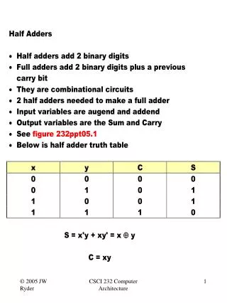
Half Adder • The half adder accepts two binary digits on its inputs A and B. • It produce two binary digits outputs, a sum bit (S) and a carry bit (C). • The simplest half-adder design, pictured incorporates an XOR gate for S and an AND gate for C. Carry <= X AND Y; Sum <= X XOR Y;
Input Output A (sum) Half Adder B C0 (carry out) Diagram Logic Symbol: Logic Diagram:
Diagram Logic Diagram: Logic Diagram:
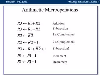
Full Adder • A full adder adds binary numbers and accounts for values carried in as well as out. • A one-bit full adder adds three one-bit numbers input , often written as A, B, and Cin; A and B are the operands, and Cin is a bit carried in. • A full adder can be constructed from two half adders by connecting A and B to the input of one half adder, connecting the sum from that to an input to the second adder, connecting Cin to the other input and OR the two carry outputs S = X xor Y xor Cin Cout = X.Y + X.Cin + Y.Cin
Input Output Cin (sum) Full Adder A B C0 (carry out) Diagrams Logic Symbol: Logic Diagram:
Diagram a Half Adder b Cout OR Half Adder Sum cin
Truth Table • S is 1 if an odd number of inputs are 1. • COUT is 1 if two or more of the inputs are 1.
Sum is `1’ when one of the following four cases is true: • a=1, b=0, c=0 • a=0, b=1, c=0 • a=0, b=0, c=1 • a=1, b=1, c=1
Circuit of Adder A B
Circuit of Adder A X B
Circuit of Adder A B ∑ Cin
Circuit of Adder A B ∑ Cin Y
Circuit of Adder A B ∑ Cin Y = A.B
Circuit of Adder A B ∑ Cin Cout Cout= (A B). Cin + A.B
X Y S Cin Cout The Full Adder
Half Adder Half Adder Cin Cin Cin + xy Cin The Full Adder