Download
1 / 31
310 likes | 458 Views
University of Palestine. Faculty of Information Technology. ITGD4103 Data Communications and Networks Lecture-13: week 14- q-2/ 2008. Dr. Anwar Mousa. Communication Channels. Fibre Optic Cable. A fibre optic cable propagates a signal as a pulse of light along a transparent medium.

E N D
University of Palestine Faculty of Information Technology ITGD4103 Data Communications and Networks Lecture-13: week 14- q-2/ 2008 Dr. Anwar Mousa Dr. Anwar M. Mousa anwar_mousa@yahoo.com
Communication Channels Dr. Anwar M. Mousa anwar_mousa@yahoo.com
Fibre Optic Cable • A fibre optic cable propagates a signal as a pulse of light along a transparent medium. • A fibre optic cable is made from a glass or plastic core that carries light surrounded by glass cladding that (due to its lower refractive index) reflects "escaping" light back into the core, resulting in the light being guided along the fibre. • The outside of the fibre is protected by cladding and may be further protected by additional layers of treated paper, PVC or metal. • This required to protect the fibre from mechanical deformation and the ingress of water. Dr. Anwar M. Mousa anwar_mousa@yahoo.com
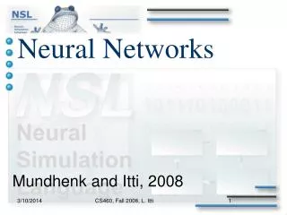
Fibre Optic Cable • Fibre optic cable consisting of a core and cladding with different refractive indices in some cases fibre optic cables are strengthened by strengthening fibres or external protective wrapping. Dr. Anwar M. Mousa anwar_mousa@yahoo.com
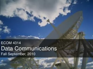
Fibre Optic Cable Fibre optic cable used to transmit a serial bit stream using pulses of light Dr. Anwar M. Mousa anwar_mousa@yahoo.com
Fibre Optic Cable • For many years it has been appreciated that the use of optical (light) waves as a carrier wave provides an enormous potential bandwidth. • Optical carriers are in the region of 10 to the power of 13 Hz to 10 to the power of 16 Hz. • In addition to the potential bandwidth, optical fibre communication offers a number of benefits: Dr. Anwar M. Mousa anwar_mousa@yahoo.com
Fibre Optic Benefits: • Size, weight, flexibility. Optical fibres have very small diameters. A very large number of fibres can be carried in a cable the thickness of a coaxial cable. • Electrical isolation. Optical fibres are almost completely immune from external fields. They do not suffer from cross-talk, radio interference, etc. • Security. It is difficult to tap into an optical line. It is extremely difficult to tap into an optical line unnoticed. • Low transmission loss. Modern optical fibre now has better loss characteristics than coaxial cable. Fibres have been fabricated with losses as low as . Dr. Anwar M. Mousa anwar_mousa@yahoo.com
Fibre Optic Benefits: • Fibre optic cables are increasingly replacing copper conductors in WANs and MANs because of their unique properties: • Lower signal loss per unit distance (resulting in longer distances between repeaters) • Higher Capacity (allowing operation at higher data rates) • Smaller physical size (allowing more fibres in a duct or trunk) Dr. Anwar M. Mousa anwar_mousa@yahoo.com
Fibre Optic disadvantages • The primary disadvantage of optical fibre are the technical difficulties associated with reliable and cheap connections. • The development of an optical circuit technology that can match the potential data-rates of the cables. • The speed of these circuits, which are electronically controlled, is usually the limiting factor on the bit-rate. • it is largely restricted to point-to-point communications. • The difficulty of connection and high-cost of associated circuitry result in optical fibres being used only in very high bit-rate communication. • In addition, good phase control of an optical signal is extremely difficult Dr. Anwar M. Mousa anwar_mousa@yahoo.com
Fibre Optic, Modes • Optical fibre is a waveguide. In simple terms, the action of a waveguide can be partially understood by considering the rays down the fibre. • A light-wave entering the fibre is either refracted into the cladding, and attenuated, or is totally internally reflected at the core/cladding boundary. In this manner it travels along the length of the fibre. • In fact, it is not possible for the wave to take any ray down the guide. Only certain rays can be taken. • These rays are called modes. For any particular frequency, there is a different ray. Dr. Anwar M. Mousa anwar_mousa@yahoo.com
Fibre Optic, Modes • The modal action of a waveguide is a consequence of the wave nature of the radiation. • A mono-mode fibre is a fibre that only has one acceptable ray-path per frequency. • A multi-mode fibre has a number of possible rays that light of a particular frequency may take. Dr. Anwar M. Mousa anwar_mousa@yahoo.com
Fibre Optic: Attenuation • The attenuation of light in the guide has a number of sources. • Absorption of light occurs in the glass and this decreases with frequency. • Scattering of light from internal imperfections within the glass -- Rayleigh scattering -- increases with frequency. • Bending the waveguide changes the local angle of total internal reflection and loss increases through the walls. Dr. Anwar M. Mousa anwar_mousa@yahoo.com
Fibre Optic: dispersion • In addition to attenuation, optical waveguides also suffer from dispersion. The dispersion has two sources. • Due to the modal behaviour, a waveguide is an intrinsically dispersive device. • Put simply, rays of different frequency travel on different paths having different lengths. • Because the different frequencies travel different lengths they take different times. • In addition to the waveguide dispersion, however, is the material dispersion. Glass is an intrinsically dispersive media. • In single mode fibres the material dispersion dominates the waveguide dispersion. Dr. Anwar M. Mousa anwar_mousa@yahoo.com
Fibre optic cable is available in three basic forms: • Stepped-index fibre. In this type of fibre, the core has a uniform refractive index throughout. This generally has a core diameter of 100 micrometer to 500 micrometer. This is a multi-mode fibre. Dr. Anwar M. Mousa anwar_mousa@yahoo.com
Fibre optic cable is available in three basic forms: • Graded-index fibre. In this type of fibre, the core has a refractive index that gradually decreases as the distance from the centre of the fibre increases. This generally has a core diameter of 50 micrometer. This is a multi-mode fibre. Dr. Anwar M. Mousa anwar_mousa@yahoo.com
Fibre optic cable is available in three basic forms: • Mono-mode fibre. As the name suggests, the distinguishing characteristic of this fibre is that allows only a single ray path. The radius of the core of this type of fibre is much less than that of the other two, however it does have a uniform refractive index Dr. Anwar M. Mousa anwar_mousa@yahoo.com
Fibre optic cable is available in three basic forms: From, 1 to 3, we find that the cost of production increases, the complexity of transmitter and receiver increases, while the dispersion decreases. This latter property change means that the mono-fibre also has the potential to provide greater bandwidth. As it becomes cheaper to produce mono-mode fibre technology, an increased use of this type of optical fibre is observed. Dr. Anwar M. Mousa anwar_mousa@yahoo.com
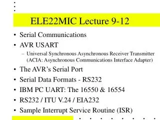
The electromagnetic spectrum; propagation in free-space and the atmosphere • In this section we shall consider the physical properties of free-space electromagnetic waves, and how the atmosphere influences the propagation of electromagnetic waves. • In the following sections, we shall describe how these properties have determined the selection of frequencies for communication. • The electromagnetic spectrum is divided up into a number of bands Dr. Anwar M. Mousa anwar_mousa@yahoo.com
The higher frequencies of the electro-magnetic spectrum Dr. Anwar M. Mousa anwar_mousa@yahoo.com
The electromagnetic spectrum; • Microwave : from 1GHz – 300 GHz • S band: 2-4 GHz • C band: 4-8 GHz • X band: 8-12 GHz • Ku band: 12-18 GHz • K band: 18-27 GHz • Ka band: 27-40 GHz • .................................................................................................. • VLF/LF band: 3 KHz - 300 KHz • MF band: 300 KHz - 3 MHz • HF band: 3 MHz - 30 MHz • VHF band: 30 MHz - 300 MHz • UHF band: 300 MHz - 3 GHz • SHF band: 3 GHz - 30 GHz • EHF band: 30 GHz - 300 GHz Dr. Anwar M. Mousa anwar_mousa@yahoo.com
The electromagnetic spectrum; • AM broadcast band(MF band). The band of frequencies extending from 535 to 1705 kHz. • The 117 carrier frequencies assigned to AM • broadcast stations begin at 540 kHz and progress in 10 kHz steps to 1700 kHz. • The FM broadcast band (VHF band) consists of that portion of the radio frequency spectrum between 88 MHz and 108 MHz. It is divided into 100 channels of 200 kHz each. • TV chennels (VHF,UHF bands) VHF(54 MHz-88 MHz, 174 MHz-216 MHz), UHF(470 MHz-806 MHz) . It is divided into 69 channels of 6 MHz each. Dr. Anwar M. Mousa anwar_mousa@yahoo.com
The electromagnetic spectrum; propagation in free-space and the atmosphere • Propagation of waves in free-space is different from that in cable or waveguides. • The power of free-space waves obey an inverse square law. For each doubling of the distance between the source and receiver, a 6dB loss is experienced. • For all frequencies up to millimetre-wave frequencies, this free-space loss is the most important source of loss. • Because of it, free-space systems usually require much more power than cable or fibre systems. Dr. Anwar M. Mousa anwar_mousa@yahoo.com
Propagation in free-space • When waves traveling in free-space are obstructed, new waves result from the interaction. There are four types of interaction: • Reflection. This occurs when a wave meets a plane object. The wave is reflected back without distortion. • Refraction. This occurs when a wave encounters a medium with a different wave speed. The direction and speed of the wave is altered. • Diffraction. This occurs when the wave encounters an edge. The wave has the ability to turn the corner of the edge. This ability of waves to turn corners is called diffraction. It is markedly dependent on frequency -- the higher the frequency, the less diffraction. Very high frequencies (light) hardly diffract at all; "light travels in straight lines." Dr. Anwar M. Mousa anwar_mousa@yahoo.com
Reflection, refraction and diffraction • Scattering. Catch-all description of wave interactions that are too complex to be described as reflection, refraction or diffraction. Typically the result of scattering is to remove radiation of the wave, and re-radiate it over a wide range of directions. Scattering too is strongly frequency dependent. Usually it will increase with frequency. Dr. Anwar M. Mousa anwar_mousa@yahoo.com
Propagation through the atmosphere • From the point of view of wave propagation, there are two layers. • Thetroposphere is the lowest layer of the atmosphere. It extends (typically) from the surface to a height of 50 Km. It contains all the Earth's weather, all the liquid water, most of the water vapour, most of the gaseous atmosphere, and most of the pollution. • The ionosphereextends from the top of the troposphere into outer space. The ionosphere plays a crucial historical role in radio communication. It consists of oxygen molecules that are ionised by the action of the sun. During the day, the quantity of ions rises. At night, the ions recombine to form uncharged oxygen molecules. Dr. Anwar M. Mousa anwar_mousa@yahoo.com
Propagation through the atmosphere • The ionisation of the atmosphere converts the ionosphere into a plasma: an electrically neutral gas of positive and negative charges. • A plasma has a wave-speed that is a strong function of frequency. • The consequence of this is that, to a low frequency wave, the ionosphere behaves as a mirror. • Waves are simply reflected. This permits a mode of propagation in which the wave bounces forwards and backwards between the ionosphere and the Earth. Dr. Anwar M. Mousa anwar_mousa@yahoo.com
Propagation through the atmosphere • It was this mode of propagation that permitted Marconi, to achieve cross-Atlantic radio communication, and, in the process, discover the ionosphere. • The Earth itself also acts as a mirror for electromagnetic waves. • As the frequency increases to around 50MHz, the ionospheric effect reduces, and at higher frequencies becomes invisible. Dr. Anwar M. Mousa anwar_mousa@yahoo.com
Propagation through the atmosphere • Using the ionosphere for radiowave propagation Dr. Anwar M. Mousa anwar_mousa@yahoo.com
High Frequency (HF, 3MHz -30MHz) propagation • The propagation of HF consists of two waves. • The sky-wave, that bounces from the ionosphere, and • the ground-wave, that propagates along the ground. • Because of the long wavelengths, HF communications are not effected by the troposhpere, and can usually bend around even large objects such as hills. • The ionosphere permits communication over great distances. Dr. Anwar M. Mousa anwar_mousa@yahoo.com
Very High Frequency (VHF) and Ultra High Frequency (UHF) propagation • These frequencies are not effected by the troposphere, but are too high to exploit the ionosphere. • In addition their decreased wavelength makes them increasingly less able to diffract around obstacles. • At UHF in particular, areas in deep radio shadow can experience very poor reception. • In urban areas, most reception is due to scattered arrivals. • Experiments have shown that the free-space loss is increased in urban areas, to the extent of following a fourth power law. • VHF is used for FM radio stations and UHF for TV transmissions. Dr. Anwar M. Mousa anwar_mousa@yahoo.com
Very High Frequency (VHF) and Ultra High Frequency (UHF) propagation • When the received signal consists of a number of scattered arrivals, an effect called fading occurs. • According to the location, the many arrivals may interfere constructively or destructively. • The phase relationship between the arrivals changes as the location of receiver changes. • This causes a moving receiver to experience fluctuations between strong and weak signals. • This effect is known as fading. Dr. Anwar M. Mousa anwar_mousa@yahoo.com