Download
1 / 56
570 likes | 896 Views
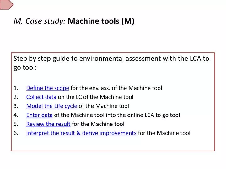
M. Case study: Machine tools (M). Step by step guide to environmental assessment with the LCA to go tool: Define the scope for the env. ass. of the Machine tool Collect data on the LC of the Machine tool Model the Life cycle of the Machine tool

E N D
M. Case study:Machine tools (M) Step by step guide to environmental assessment with the LCA to go tool: • Define the scope for the env. ass. of the Machine tool • Collect data on the LC of the Machine tool • Model the Life cycle of the Machine tool • Enter data of the Machine tool into the online LCA to go tool • Review the result for the Machine tool • Interpret the result & derive improvements for the Machine tool
Case study:Machine tools (M)M.1. Define the scope Substeps: • Define the goal of the study • Define the functional unit • Define the reference flow • Define the product system and the unit processes • Draw a process tree • Define the system boundaries of all 5 life cycle stages • Define other requirements
M.1.a. Defining the Goal for an environmental assessment of the Machine tool Why: To generate an environmental profile of the machine tool and identify the key environmental issues. Who: Designers and engineers working on the upgrade of the current & development of future models of the machine tool. What: Use the results to derive product improvements and compare different generations of the machine tool with respect to their environmental performance.
M.1.b. Defining a Functional unit for an environmental assessment of the Machine tool The product function of the Machine tool is to machine materials. There are a wide range of machine tools such as grinding, drilling, milling, (laser) cutting or electro discharge machining tools. Since all fashion different workpieces, the only relevant functional unit they all share is the operation of the machine in a specified shift regime over the lifetime of the machine. A shift regime defines the amount of time the machine tool spends in the three main operating states, „Production“, Ready“ and „Standby“ in a fixed period. The Functional unit is therefore defined as: One machine tool over the entire machine lifetime, in a declared shift regime, specifying the number of shifts over the lifetime and the amount of time spent in the three main operating states „Production“, „Ready“ and „Standby“ in a shift.
M.1.c. Defining a Reference flow for an environmental assessment of the Machine tool The reference flow is a measure of the amount of product needed to realize the function as indicated in the functional unit. Since the functional unit is the operation of the machine tool over one hour in a specified shift regime, the reference flow contains all the materials, energy and processes necessary for this. Materials contained in the machine tool, Energy and materials needed for manufacturing of the machine tool, Transport of the machine tool and the packaging needed, the electricity consumption while the machine tool is in use.
M.1.d.Defining the Product system and Unit processesfor the Machine tool Define the individual processes involved in the machine tool over its lifetime • Material: Components of the machine tool and the contained materials • Foot: Cast iron, Sand • Housing: Al, Flat glas, Polycarbonate • Workpiece-holder: Steel, Electric motor • Tool-holder: Steel, Electric motor • Electronic control unit: Cu, Electronics, PP • Manufacture: Energy used and waste generated • Electricity used in production • Steel and Iron shavings as waste • Distribution: Method and packaging • Transoceanic freight ship and truck • Wood crate for shipping • Use: Energy use and material consumption in the use stage • Electricity required in use stage • End of life: Recycling possible • Recycling of the materials declared in the Materials stage
M.1.e. Drawing the process tree for the Machine tool Materials *Itiscustomary not toshowEnergyand Transport processes in theprocesstree. Data collection must includetheseprocesses.
M.1.f. System boundary of the 5 life cycle stages for the Machine tool • Materials • Includes natural resource extraction and pre-processing of raw materials used in the machine tool. • Excludes the transport & packaging of the raw materials from pre-processing to the manufacturing plant due to data gaps. • Manufacture • Includes the energy needed for processing of the materials as delivered to the manufacturer and the assembly of the machine tool at the manufacturing plant. (e.g. Drilling, welding, …) • Includes the waste generated in the manufacturing process. • Includes the resource consumption needed in manufacturing (e.g. oil, welding gases, etc.) • Distribution • Includes the shipment from the manufacturer to the customer as well as packaging. • Excludes the energy needed for packaging or the setup at the customer site. • Use • Includes the electrical energy and the operating resources during the entire lifetime of the machine tool. Several shift regime scenarios are considered. • End-of-Life • Includes energy and consumables needed for recycling. Benefits are included in the materials stage through the choice of recycled materials as input. • Excludes energy needed for disassembly and transport of materials to recycling facility.
M.1.g. Other requirements for the System boundary for the Machine tool • Temporal boundary: • Latest available data • Geographical boundary: • Material sourcing and Manufacture in Europe. Global Distribution and Use. Representative data to be used. • Technological boundary: • Focus on one technology / specific type of machine tool only
Case study:Machine tools (M)M.2. Collect Data Substeps: • Identify necessary data • Define the depth and quality of data needed • Identify & keep track of data source • Identify and track the data quality
M.2.a.i. Identify necessary data for the environmental assessment of the Machine tool
M.2.a.ii. Defining the rule for mass inclusionfor the Machine tool Decisionruleformassinclusion: 99% of total weight
M.2.b. Define the depth and quality of data needed for the environmental assessment of the Machine tool
M.2.c. & M.2.d. Identify & keep track of the data source and the data quality for the environmental assessment of the Machine tool
Case study:Machine tools (M)M.3. Model the Life Cycle Substeps: • Review available data and bring it into a useful format, making assumptions where necessary • Develop Scenarios for the Distribution stage • Develop Scenarios for the Use stage • Develop Scenarios for the End-of-Life stage
M.3.a. Review available data and bring it into a useful format, making assumptions where necessary for the Machine tool
M.3.b. Distribution scenario development for the environmental assessment of the Machine tool A single distribution scenario is developed: In this example, the machine tool is produced in Germany, and delivered to Sweden. The machine tool was transported from Germany to Sweden. The transport distance is assumed to be 1000km by road transport.
M.3.c. Use scenario development for the environmental assessment of the Machine tool To evaluate the entire life cycle of the machine tool, one must assume certain use scenarios. In this case study, a common scenario for a production site in Sweden is assumed. In the LCA to go tool, you can add up to 3 different scenarios. 2 Shift regime, Sweden: Production 12 h/d, Ready 4 h/d, Standby 2 h/d, Off 6 h/d
M.3.d. End-of-Life scenario development for the environmental assessment of the Machine tool This Scenario consists of different paths for each raw material. Usually the big components of the machine tool such as most metal parts and electronic components are easy to recycle. In contrast to these parts, Plastics will usually go to incineration, and some inert materials will be disposed on landfills.
Case study:Machine tools (M)M.4. Enter data Substeps: • Enter data for all 5 life cycle stages and define data quality • Understand why the data is needed and what happens with the entered data
M.4.a. Enter data for all 5 life cycle stages for the Machine tool A video tutorial on how to enter data into the online tool for machine tools is available at: Watch a demonstration video The following slides will give you a short overview on the rough and detailed assessment. Based on this case study you will see how to enter the data for the 5 Life Cycle Stages: Materials, Manufacturing, Distribution, Use, and End-of-life.
M.4.a.i. Rough assessment / Detailed assessment • The LCA to go tool works as a two step iterative process. The first step is to do the rough assessment, through which we can identify the major environmental impacts. The second step is the Detailed assessment where we will focus on the environmental hotspots. Following the results or improvements, the Detailed assessment can be repeated.
M.4.a.ii. Rough assessment Before enterign the data, we have to register and log in to the web tool. We create an new product, and indicate the main specifications of the machine tool. In this case study, we investigate a grinding machine. We select the industrial sector “machine tools”, define the machine tool: “Grinding Machine” and choose the option “Rough assessment”. The rough assessment will give us a first impression of the environmental profile of the machine tool. Thereafter we can decide which data should be improved in the detailed assessment later. It only takes 10 minutes.
M.4.a.iii. Life Cycle Stage 1: Materials • Main materials & Parts: • Cast iron: 13.000kg • Steel: 3.120kg • Aluminium: 120kg • Electronics: 500kg • Electric motor: 150kg The main materials and supplier parts of our example are shown in the list above. We add all the main materials in the “LCA to go” tool. For example, in this case study, the parts of the machine tool, such as the Workpiece-holder, the Tool -holder, and the Machine-foot contain approximately 13.000kg iron.
M.4.a.iv. Life Cycle Stage 1: Materials • Main materials & Parts: • Cast iron: 13.000kg • Steel: 3.120kg • Aluminium: 120kg • Electronics: 500kg • Electric motor: 150kg We add the supplier parts into the “LCA to go” tool.
M.4.a.v. Life Cycle Stage 2: Manufacturing The machine tool is produced in Germany. 25.000 kWh are consumed in manufacturing for diverse metal working processes and for assembly. In this example there are 2.000 kg waste from manufacturing in the form of metal chippings.
M.4.a.vi. Life Cycle Stage 3: Distribution The machine tool is delivered to Sweden by truck, we select the option “Overland”. In the rough assessment a distance estimate is made by the tool. For delivery, the machine tool is packed into PE-foil. We enter the approximate amount of packaging material used.
M.4.a.vii. Life Cycle Stage 4: Use The exact modelling of the use stage is important for the robustness of the results. As previous investigations have shown, the major environmental impact of machine tools comes from the use stage. • The electrical power consumption is taken from the product data sheet for the three different operating states. The manufacturer use the machine tool 250 working days per year and produces on average 6 parts per hour.
M.4.a.viii. Life Cycle Stage 4: Use 12 hours per day the machine tool is "Processing”, 4 hours per day it is “Ready for operation”, 2 hour per day on “Standby”, and 6 hours it is switched “Off”.
M.4.a.ix. Life Cycle Stage 5: End-of-Life We assume a realistic End-of-life scenario. It is safe to assume for machine tools that the great majority of contained materials can easily be recycled, we select the option “Recycling”. • Data Quality: The Data Quality Indicator We enter the Data Quality Indicator for each life cycle stage and define whether the data is “Robust”, “Indicative”, or “Illustrative”.
M.4.a.x. Analysis, Results: Rough assessment It can be clearly seen that the major environmental impact comes from the Use Stage. Typically a machine tool is a use intensive product. We have to be sure that we have the most robust data for the most important life cycle stages. In this case study we have identified the environmental hotspot, but the data is only “Indicative”, so we will try to collect further data and improve the level of detail and robustness of the result, through the Detailed assessment.
M.4.a.xi. Detailed assessment We create a new product and choose the option “Detailed assessment”. In this model we use more detailed data and focus on the stages with the biggest environmental impacts identified in the rough assessment to achieve a more detailed and robust environmental profile. The results will enable us to draw the right conclusions and identify the fitting improvement options.
M.4.a.xii. Life Cycle Stage 1: Materials We define the main components and the contained materials of the machine tool. The machine tool consists of 9 components: the Workpiece-holder, the Tool-holder, the Machine-foot, the Housing, the Control cabinet, 3 predefined supplier parts and the Oil mist extractor. Below you can see the materials contained in the Workpiece-holder and 3 predefined supplier parts.
M.4.a.xiii. Life Cycle Stage 1: Materials The Oil mist extractor is not a predefined supplier part, therefore we have to define it in the tool. In this case, the transport distance from the manufacturer to our plant is 1 000 km. Once the transport distance has been defined, the oil mist extractor will appear in the list of user-defined supplier parts, and we add the materials and the processes that are required to produce it.
M.4.a.xiv. Life Cycle Stage 2: Manufacturing We add the main manufacturing processes that are used at our own manufacturing plant and the weight of material that is removed in chipping processes such as Milling, Drilling, and Turning, as well as the amount of material that is processed in non-chipping processes such as Sheet rolling or Wire drawing.
M.4.a.xv. Life Cycle Stage 2: Manufacturing Additionally, 1000 kWh manufacturing energy is required to assemble the machine tool. 200 kWh overhead energy per machine tool are estimated for Air Conditioning, Lighting, Heating the manufacturing line,...
M.4.a.xvi. Life Cycle Stage 2: Manufacturing In this case, 9.3% of the material input is wasted in manufacturing.
M.4.a.xvii. Life Cycle Stage 3: Distribution The machine tool is distributed to Sweden by truck, the transport distance is assumed to be 1000 km. For distribution the machine tool is packed into 150 kg PE foil. The End of life scenario here refers to the packaging material. It can either be Recycled, Incinerated or sent to Landfill
M.4.a.xviii. Life Cycle Stage 4: Use From measurement according to ISO 14955 we derive that the machine tool needs 30 kW electrical power in “Processing”, 10kW in “Ready for operation” and 0.3 kW in “Standby” modes. We enter the correct location and the corresponding electricity grid mix. As seen in the rough assessment, the use stage is the most important life cycle stage. Inaccuracies will have a huge impact on the results.
M.4.a.xix. Life Cycle Stage 4: Use A Shiftregimescenariodescribestheuseofthemachinetool. In theDdetailedassessment, threescenarioscanbedefinedtoinvestigate different useintensities, create a betterunderstandingoftheimpactoverthelifetimeandcustomizetheresulttospecificconditions.
M.4.a.xx. Life Cycle Stage 4: Use The machine tool needs 1 m3/h compressed air in the operating state “Processing” and 0.5 m3/h in “Ready for operation”. Further the machine tool consumes 0.001 kg/h lubrication oil for lubrication. The impact of these inputs also flows into the overall impact over the life cycle.
M.4.a.xxi. Life Cycle Stage 4: Use • To derive improvement measures, the electrical power consumption has to be split up into the different sub-systems.
M.4.a.xxii. Life Cycle stage 5: End-of-Life As described in the End-of-Life scenario, the metal parts and electronic components of the machine tool are recycled at the end of its life, the plastics will get incinerated, and some inert materials may be disposed on a landfill.
M.4.a.xxiii. Life Cycle stage 5: End-of-Life We note the parts that are recycled, incinerated, ore disposed of in a landfill. Commonly, the majority of machine tool components are recycled. For each part, we can define an own end of life scenario.
M.4.b. What happens with the data entered for the Machine tool The data that is entered is multiplied with the corresponding Datasets from the Life Cycle Inventory Database to give the Environmental impact for this specific part of the life cycle. The total impacts can be summed over the life cycle stages to give the overall environmental load of the product. In the case of the machine tool, the Cumulative Energy Demand (CED) is used to describe the environmental load.
M.5. Case study:Machine tools (M)M.5. Review the results Substeps: • Understand the first result & the available impact categories • Identify major environmental hotspots and the robustness of the underlying data • Collect and enter additional data where necessary
Case studynavigation M.5.a. Understand the first result & the available impact categories for the Machine tool For the machine tools, the KEPI of Cumulative Energy Demand (CED) is used to describe the environmental impact of the product. Having entered much more detailed data, we have a greater depth and level of detail in the results, compared to the rough assessment. Start page
M.5.b. Identify major environmental hotspots and the robustness of the underlying data for the Machine tool The major environmental hotspot is the electricity consumption in the Use stage, followed by the raw materials used in the Materials stage. The data used to calculate the environmental impacts of these stages is robust. The result can therefore be considered as robust.
M.5.c. Collect and enter additional data where necessary for the Machine tool The below table describes the improved data. In contrast to the Rough assessment, it was necessary to collect additional data for the Use stage.
M.6. Case study:Machine tools (M)M.6. Review the results Substeps: • Draw conclusions from the result • Derive appropriate improvement measures • Prepare the result for distribution / communication