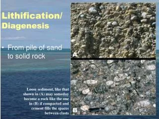
Download

1 / 27
270 likes | 416 Views
CEE 598, GEOL 593 TURBIDITY CURRENTS: MORPHODYNAMICS AND DEPOSITS. LECTURE 6 HYDRAULICS AND SEDIMENT TRANSPORT: RIVERS AND TURBIDITY CURRENTS. Head of a turbidity current in the laboratory. From PhD thesis of M. H. Garcia.

E N D
CEE 598, GEOL 593 TURBIDITY CURRENTS: MORPHODYNAMICS AND DEPOSITS LECTURE 6 HYDRAULICS AND SEDIMENT TRANSPORT: RIVERS AND TURBIDITY CURRENTS Head of a turbidity current in the laboratory From PhD thesis of M. H. Garcia
STREAMWISE VELOCITY AND CONCENTRATION PROFILES: RIVER AND TURBIDITY CURRENT u = local streamwise flow velocity averaged over turbulence c = local streamwise volume suspended sediment concentration averaged over turbulence z = upward normal direction (nearly vertical in most cases of interest) z z
VELOCITY AND CONCENTRATION PROFILES BEFORE AND AFTER A HYDRAULIC JUMP The jump is caused by a break in slope Garcia and Parker (1989)
A u utA x ut VOLUME FLUX OF FLOWING FLUID AND SUSPENDED SEDIMENT The flux of any quantity is the rate at which it crosses a section per unit time per unit area. So flux = discharge/area The fluid volume that crosses the section in time t is Aut The suspended sediment volume that crosses is cAut The streamwise momentum that crosses is wuAut The fluidvolume flux = u The suspended sediment volume flux = uc The streamwise momentum flux = wu2
LAYER-AVERAGED QUANTITIES: RIVER In the case of a river, layer = depth H = flow depth U = layer-averaged flow velocity C = layer-averaged volume suspended sediment concentration (based on flux) Now let qw = fluid volume discharge per unit width (normal to flow) qs = suspended sediment discharge per unit width (normal to flow) discharge/width = integral of flux in upward normal direction
FOR A RIVER: Flux-based average values U and C Or thus z
LAYER-AVERAGED QUANTITIES: TURBIDITY CURRENT The upper interface is diffuse! So how do we define U, C, H?
USE THREE INTEGRALS, NOT TWO Let qw = fluid volume discharge per unit width qs = suspended sediment discharge per unit width qm = forward momentum discharge per unit width Integrate in z to “infinity.” z
FOR A TURBIDITY CURRENT Three equations determine three unknowns U, C, H, which can be computed from u(z) and c(z).
BED SHEAR STRESS AND SHEAR VELOCITY Consider a river or turbidity current channel that is wide and can be approximated as rectangular. The bed shear stress b is the force per unit area with which the flow pulls the bed downstream (bed pulls the flow upstream) [ML-1T-2] The bed shear stress is related to the flow velocity through a dimensionless bed resistance coefficient (bed friction coefficient) Cf, where The bed shear velocity u [L/T] is defined as Between the above two equations, where Cz = dimensionless Chezy resistance coefficient
SOME DIMENSIONLESS PARAMETERS D = grain size [L] = kinematic viscosity of water [L2/T], ~ 1x10⁻⁶ m2/s g = gravitational acceleration [L/T2] R = submerged specific gravity of sediment [1] Froude number ~ (inertial force)/(gravitational force) Flow Reynolds number ~ (inertial force)/viscous force): must be >~ 500 for turbulent flow Particle Reynolds number ~ (dimensionless particle size)3/2
SOME DIMENSIONLESS PARAMETERS contd. Shields number ~ (impelling force on bed particle/ resistive force on bed particle): characterizes sediment mobility Now let c denote the “critical” Shields number at the threshold of motion of a particle of size D and submerged specific gravity R. Modified Shields relation:
SHIELDS DIAGRAM The silt-sand and sand-gravel borders correspond to the values of Rep computed with R = 1.65, = 0.01 cm2/s and D = 0.0625 mm and 2 mm, respectively. motion no motion
CRITERION FOR SIGNIFICANT SUSPENSION But recall where and Thus the condition and the relation of Dietrich (1982): specifies a unique curve defining the threshold for significant suspension.
SHIELDS DIAGRAM WITH CRITERION FOR SIGNIFICANT SUSPENSION Suspension is significant when u/vs >~ 1
NORMAL OPEN-CHANNEL FLOW IN A WIDE CHANNEL Normal flow is an equilibrium state defined by a perfect balance between the downstream gravitational impelling force and resistive bed force. The resulting flow is constant in time and in the downstream, or x direction. • Parameters: • x = downstream coordinate [L] • H = flow depth [L] • U = flow velocity [L/T] • qw = water discharge per unit width [L2T-1] • B = width [L] • Qw = qwB = water discharge [L3/T] • g = acceleration of gravity [L/T2] • = bed angle [1] tb = bed boundary shear stress [M/L/T2] • S = tan = streamwise bed slope [1] • (cos 1; sin tan S) • w = water density [M/L3] The bed slope angle of the great majority of alluvial rivers is sufficiently small to allow the approximations
THE DEPTH-SLOPE RELATION FOR NORMAL OPEN-CHANNEL FLOW Conservation of water mass (= conservation of water volume as water can be treated as incompressible): Conservation of downstream momentum: Impelling force (downstream component of weight of water) = resistive force Reduce to obtain depth-slope product rule for normal flow:
THE CONCEPT OF BANKFULL DISCHARGE IN RIVERS Let denote river stage (water surface elevation) [L] and Q denote volume water discharge [L3/T]. In the case of rivers with floodplains, tends to increase rapidly with increasing Q when all the flow is confined to the channel, but much less rapidly when the flow spills significantly onto the floodplain. The rollover in the curve defines bankfull discharge Qbf. Bankfull flow ~ channel-forming flow??? Minnesota River and floodplain, USA, during the record flood of 1965
PARAMETERS USED TO CHARACTERIZE BANKFULL CHANNEL GEOMETRY OF RIVERS In addition to a bankfull discharge, a reach of an alluvial river with a floodplain also has a characteristic average bankfull channel width and average bankfull channel depth. The following parameters are used to characterize this geometry. Definitions: Qbf = bankfull discharge [L3/T] Bbf = bankfull width [L] Hbf = bankfull depth [L] S = bed slope [1] Ds50 = median surface grain size [L] n = kinematic viscosity of water [L2/T] R = (rs/r – 1) = sediment submerged specific gravity (~ 1.65 for natural sediment) [1] g = gravitational acceleration [L/T2]
SETS OF DATA USED TO CHARACTERIZE RIVERS Sand-bed rivers D 0.5 mm Sand-bed rivers D > 0.5 mm Large tropical sand-bed rivers Gravel-bed rivers Rivers from Japan (gravel and sand)
SHIELDS DIAGRAM AT BANKFULL FLOW Compared to rivers, turbidity currents have to be biased toward this region to be suspension-driven!
FROUDE NUMBER AT BANKFULL FLOW Turbidity currents?
DIMENSIONLESS CHEZY RESISTANCE COEFFICIENT AT BANKFULL FLOW Turbidity currents?
DIMENSIONLESS WIDTH-DEPTH RATIO AT BANKFULL FLOW Turbidity currents?
THE DEPTH-SLOPE RELATION FOR BED SHEAR STRESS DOES NOT NECESSARILY WORK FOR TURBIDITY CURRENTS! In a river, there is frictional resistance not only at the bed, but also at the water-air interface. Thus if I denotes the interfacial shear stress, the normal flow relation generalizes to: But in a wide variety of cases of interest, I at an air-water interface is so small compared to b that it can be neglected.
A TURBIDITY CURRENT CAN HAVE SIGNIFICANT FRICTION ASSOCIATED WITH ITS INTERFACE If a turbidity current were to attain normal flow conditions, where and Cf denotes a bed friction coefficient and Cfi denotes an interfacial frictional coefficient. But turbidity currents do not easily attain normal flow conditions!
REFERENCES Garcia and Parker (1989)