Download

1 / 41
410 likes | 413 Views
Modeling Approaches to Vacuum Arc Plasma. Michael Keidar Mechanical & Aerospace Engineering The George Washington University. In collaboration with: I. I. Beilis, R.L. Boxman, M.B. Schulman, E. Taylor, P. Slade, T. Zhuang, A. Shashurin,. Acknowledgement: NSF, NASA, AFOSR.

E N D
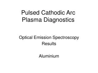
Modeling Approaches to Vacuum Arc Plasma Michael Keidar Mechanical & Aerospace Engineering The George Washington University In collaboration with: I. I. Beilis, R.L. Boxman, M.B. Schulman, E. Taylor, P. Slade, T. Zhuang, A. Shashurin, Acknowledgement: NSF, NASA, AFOSR
Smartphone summary: vacuum arc plasmas are quite complicated thus multiple approaches are required
Vacuum Arc Arc attaches to cathode at micron-sized spots called cathode spots At low current (up to 100 A for copper) one spot is formed at a time Current density at spot is 109 – 1012 A/m2 Spot lifetime ranges from nanoseconds to microseconds Cathode Spot 10 mm 3 Juttner, J. Phys. D, 2000 Beilis, IEEE Trans. Plasma Sci., 2001
High Arc Current Vacuum Arc Columnar arc • >1 kA • Transition to the diffuse mode • Magnetic field effect • Plasma model • Expansion of individual cathode jets • Formation of common channel from overlap • Single jet in the presence of high-current column (imposed voltage on single jet) and magnetic field cathode Diffuse arc cathode
The Free Boundary Model Assumptions Steady-state, fully ionized, collision dominated, quasi-neutral plasma Anode acts as a passive current and particle collector Cathode spots act as source of plasma at a specified jet angle and velocity Cathode spots evenly distributed (no arc constriction) within a circular area Magnetized electrons, unmagnetized ions External magnetic field purely axial and uniform, self field purely azimuthal Numerical methods Iterative scheme for solving for the potential Implicit second-order accuracy method to calculate the velocity, current density, and density from the potential Two approaches: self consistent solution voltage is set by high-current column 5 Keidar et al, J. Phys. D, 1996
Free plasma jet boundary M. Keidar et al, J. Phys. D, 1996 M. Keidar and I. I. Beilis, Plasma Engineering, Elsevier, 2013
Focusing and Arc Voltage Ring anode anode cathode Disk anode Experiment: Heberlein and Porto, IEEE Trans. Plasma Sci., 11, 152 (1983) Keidar et al, J. Phys. D, 1996; J. Appl. Phys., 1998; IEEE TPS, 1997
Multiply charged ion transport Mean ion charge state generally >1 Time-of-flight Mean Charge along the jet Keidar & Brown, Rev. Sci. Instr. 2000
Comparison with Experiment anode cathode Experiment: V.M. Khoroshikh, Sov. Phys. Tech. Phys., 33(6) 723 (1988) Keidar, J. Appl. Phys. 1998; Rev. Sci. Instr. 2000
rjet (L, Bcr) = h (Iarc, Ra) L is the gap length rjet(L, B) is the increase of the plasma jet radius due to the radial expansion 2h(Iarc , Ra) is the distance between two individual adjacent channels Condition for critical AMF Ro + rjet Bcr B*
Columnar & Diffuse Arc in a Magnetic Field Plasma density V-shape voltage characteristic B Model prediction Gundlach, ISDEIV, 1972 Keidar & Schulman, IEEE Trans. Plasma Sci, 2000, 2001
High-current vacuum arc • Two-dimensional free expansion of the plasma jets • Voltage is calculated for the individual jets and high-current column • Diffuse column arc: Expansion of single cathodic jet burning in parallel to high current column
Anode sheath potential drop =Teln[jth(r,z)/j(r,z)] jth(r,z) electron thermal current depends on density j(r,z) current density Single jet existence criteria =0, I=Icr I > Icr the isolated jet extinguishes I < Icr the isolated jet is stable, which is characteristic of diffusing arcs Anode sheath potential drop Anode sheath potential drop Critical arc current Keidar et al, IEEE Trans. Plasma Sci, 2004
Critical voltage Critical voltage as a function of gap length Comparison with experiment calculated Vcr Observed onsets of non-diffuse arcing measured Varc< Vcr – is diffuse arc condition Experiment M. B. Schulman and H. Schellekens, 2000 Keidar et al, IEEE Trans. Plasma Sci, 2004
Comparison with experiment Varc< Vcr – is diffuse arc condition
Arc Voltage Criterion • Single jets appear even when • Single jet appearance is common phenomenon during evolution into a high-current diffuse arc • More general criterion is required based on effective voltage Varc>Vcr
Comparison with experiment Generalized condition agrees better with observations
Radial plasma flow Kimblin & Voshall,Proc. IEE, 119, 1754 (1972)
The model Similar to the model of the interelectrde gap • hydrodynamic • multicomponent plasma • ambipolar flow Potential distribution: dU/dr = kTe/eln(Zjnj) + Be(ZjnjVj/Zjnj) Density gradient Magnetic Field
Radial Flow 20 eV peak good agreement Rustenberg et al. IEEE Trans. Plasma Sci., 1995
Material ablation:non-equilibrium layer Existing models (Langmuir) can describe only low pressure <1 torr cases Knudsen layer ~few mean free paths The back flux b is generated due to collisions b o To Evaporation flux: ev= o- b Keidar et al, J. Appl. Phys., 2001
Non-equilibrium layer x f1 Equilibrium plasma f(x) fo Boundary conditions Vxf(V) dV = const (mass) Vx2f(V)dV = const (momentum) VxV2 f(V)dV = const (energy) Keidar et al, J. Appl. Phys., 2001
Kinetic model of the Knudsen Layer U1 f2 Analytical and particle (DSMC) approaches: f(x,V) = (x)f1(V) + (1 - (x))f2(V) where (x=0)=1 and (L)=0 with x=0 [Mott-Smith, 1951] f1(V) = no3/2exp(-V2) Vx>0 f1(V) = f2(V) Vx<0 f2(V) = n13/2exp( -(v-U)2) [Anisimov, 1968] Sound speed is assumed ! f1 Depends on velocity Keidar et al, J. Appl. Phys., 2001
Thermal conductivity Carbon 900 m Ti Al Kinetic model of Knudsen layer: effect of thermal conductivity VDF in plasma T Effect of thermal conductivity Layer structure Pekker, Keidar et al. J. Appl. Phys. 2008 Keidar et al, J. Appl. Phys., 2001, 2004
Hydrodynamic Layer 1D limit U1 depends on the specifics of acceleration (n2, j) Teflon Z306 Keidar et al. J. Phys.D, 2001, J. Appl. Phys. 2001, 2004
Model validation-directed energy • Al alloy • Pulse duration 15 ns, = 308 nm, Fluence 1-10 J/cm2 • Dou et.al., IEEE J. Quantum Electron. 6, 689 2000 • Cu • Pulse duration 6 ns, = 532 nm, Fluence 10-200 J/cm2 • Semerok et.al., Laser Part. Beams 20, 67 2002
Predicting charring Condition: kT2n2 <kT1n1 and n1>n2 If backflux is higher than the primary flux –deposition Deposition rate = - m(kT2/m)0.5nC2 Ablation rate Backflux in Teflon micro-thruster Keidar et al. J. Prop. Power 2004, p. 978
Effect of cross flow (moving target) • Back flux decreases with the increase of cross flow velocity • vapor temperature at KL outer edge decreases with the increase of cross flow velocity • Ablation rate increases
Schematic of the μCT Feed Mechanism Isolation Material Magnetic Coil Core Anode Spring Cathode Isolator
Cathode Spot Rotation 34 The Experiment Result shown that the Rotation Speed is 75m/s The Rotation As the Direction of –J×B
Cathode Spot Rotation Uniform erosion
PIC simulations Magnetic field No magnetic field
NASA Ames PhoneSat Experiment Orbitals’ Antares, April 2013 • NASA Ames PhoneSat selected micro-CAT Android app compatible with PhoneSat Bus will be capable of commanding uCATs NASA ARC, August 2013
Unipolar Arcs Schwirzke, Rev. Sci. Instr. 1999 Wang, Brown, Rev. Sci. Instr. 1999
Unipolar Arc Suppression IEEE TPS, 2003
Summary • Free boundary plasma jet expansion model developed in 90s still useful • Predicts high-current vacuum arc behavior • Kinetic erosion model • Some new devices based on vacuum arcs • Unipolar arcs suppression