Download
1 / 12
120 likes | 322 Views
LHC Beam Dump System Kicker maintenance and spares. Laurent DUCIMETIERE. with contributions by: Etienne CARLIER, Volker MERTENS. References to talk by V. MERTENS, LHC Technical Committee (LTC) held on 24th October 2007 http://ab-div.web.cern.ch/ab-div/Meetings/ltc/2007/ltc_2007-16d.pdf.

E N D
LHC Beam Dump SystemKicker maintenance and spares Laurent DUCIMETIERE with contributions by: Etienne CARLIER, Volker MERTENS References to talk by V. MERTENS, LHC Technical Committee (LTC) held on 24th October 2007 http://ab-div.web.cern.ch/ab-div/Meetings/ltc/2007/ltc_2007-16d.pdf
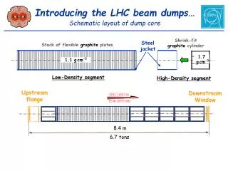
LHC Beam Dumping System (LSS6L/R, schematic) Not to scale ! MKD V-defl, 2.4 mrad H-defl, 0.3 mrad
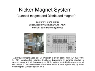
MKD pulse generators FHCT stack with trigger transformer 1 complete spare generator in place per 15 operational; replacement itself quick, but must be followed by fine-adjustment of parameters and in-depth revalidation of the dump system.
Extraction kickers MKD Granularity and “one-off redundancy” (7 TeV extraction still clean if 1 of 15 MKD fails during dump action) but failing unit must be repaired before dump system can be re-qualified for use. total (15 magnets) horizontal deflection 0.28 mrad
MKD kickers – intervention related aspects, spares Lots of I/XPOC (internal/external post-operational checks, at each dump action) to detect slow degradation. E.g. : - loss of capacity (self-healing capacitors) - broken FHCT in stack - erosion of high-current contacts Analysis must be thorough, and results must be taken serious; Failures (magnets, as the rest of the system, thoroughly tested; normally no “early faults” expected): - vacuum leak on ceramic vacuum chamber - HV flash-over at HV coil - HV coaxial cable breakdown
MKD kickers– intervention related aspects, spares Spares: - 2 complete generators for 30 operational units - 2 complete magnets for 30 operational units - 5 ceramic chambers (long lead time items) for 30 operational units - 1 spare cable already in place per magnet (per bundle of 8 cables) Replacement of a magnet/chamber involves (everything x 5 (vacuum sub-sectoring)): - dismantling of the opposite chamber - bake-out of the ceramic chamber - remounting of the new magnet and testing - remounting of the opposite chambers and bake-out of those time estimate: 2-3 weeks
MKD spares This list (like all others) is for the complete units and those components which can be fitted in situ. Besides those there are further spare components for repair of broken units in the laboratory (notably long-lead time items involving many fabrication steps like cores, HV coils, …). *) replacement itself fairly quick, but every repair affecting the impedance of the HV circuit must be followed by fine-adjustment of parameters (and in-depth re-validation of the dump system).
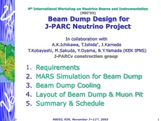
Dilution kickers MKBH, MKBV Each tank houses 2 magnets extracted beam circulating beams
MKB spares MKBH during insertion Very similar basic components as MKD (cores, coils, …) … but in a vacuum tank. Failures similar as well … Will have a lot of spares in 2008 … (until the staged equipment will be installed and operational).
Electronics & controls Have at least 1 spare for each electronics module used (≈ 150 different types, incl. PLCs). Typical spare level 10 %. Crates, CPUs, timing modules, … managed by AB/CO (not discussed here). About MTBF: assembly errors sorted out, first “burn-in” made initial wave of faults mainly over failures over lifetime: new type of equipment, statistics not well known Low power electronics not expected to fail frequently (if not over-rated …), also PLC (2 mods br.) More wear for power and high-voltage equipment (trigger modules, charging power supplies). Should consider to purchase a few further charging supplies to bridge the time when a broken one is sent away for repair, and still keeping the test stands in 867 operational. Have to see how electronics ages in the tunnel (dust, humidity, contact corrosion, …) CERN wide central storage for common equipment would be useful e.g. all SIEMENS PLC stuff in a place in 874, as already initiated possible rotation of equipment with manufacturer can avoid a number of problems
Summary Main choices on number of spares were made in the mid 90 (similar to the SPS policy). In some cases (e.g. MKB) more parts where “added on the fly” allowing to complete a full spare magnet tank (less downtime because repair can be done off-line). Number of full spare units seems generally correct: “canonical value” ≈ 10 % In reality 5 – 15 % (more if the devices are difficult or time-consuming to repair (and vice versa)) No “full spares of spares” for everything … … but typically a reasonable number of additional sub-components to repair failing units. Early numbers based on SPS experience – to be confirmed during LHC operation. Failure risk to be re-assessed, and strategy to be adapted as needed. Regular “spares reviews” to be made. Various things to be organised (responsibilities, storage, re-testing frequency, re-plenishing, …). Certain items could profit from a more central management (e.g. PLC accessories in CCC). Would a more centrally organised spares mgmt also be useful for other hardware elements ?
Issues to be addressed Hardware aspects : Certain sub-assemblies to be pre-fabricated for faster intervention. Kicker HV circuitry: erosion of high-current contacts is a recurring risk – watch out. Organisational aspects : Where to store spares: centrally in lab, or distributed in the galleries ? Centrally less effort to manage and keep hardware alive less costly as well (less duplication, e.g. electronics partly in common with PS/SPS) … but downtime is usually longer. Transport team needed (for heavy stuff). Spares “stewardship” ? test the equipment regularly to make sure it still works; apply changes on oper. eqpt. Who is responsible for “spares management” ? prevent loss of knowledge from turn-over / departure of personnel … Clear identification of components bar code system (discussed since long …) ? MTF should be helpful to trace history of (re-)used components … Regular review of spare situation and strategy in the group (at least).