Download
1 / 1
10 likes | 148 Views
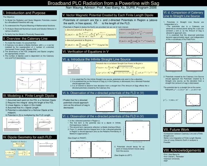
Broadband PLC Radiation from a Powerline with Sag. I. Introduction and Purpose. The Objective: To Model the Radiation and Vector Magnetic Potentials created by a Broadband Powerline with sag. To understand the Physical Meaning of Mathematical Solutions

E N D
Broadband PLC Radiation from a Powerline with Sag I. Introduction and Purpose • The Objective: • To Model the Radiation and Vector Magnetic Potentials created by a Broadband Powerline with sag. • To understand the Physical Meaning of Mathematical Solutions • To Analyze Observed Numerical results and Solution Behavior in various situations • To Verify that the Model is Physically Reasonable. Nan Maung, Advisor: Prof. Xiao-Bang Xu, SURE Program 2006 VI. d. Comparison of Catenary Line to Straight Line Source V. Vector Magnetic Potential Created by Each Finite Length Dipole • Potentials of concern are the x- and z-directed Potentials in Region a (above the earth, in free space). is the length of the FLD. • Potentials in Region b (below the Earth) are provided, but are not of main interest. • 1. Potentials in Straight Line Source are Independent of x. • The potentials due to a Catenary are observed at several points along the x-axis (for constant y and z); as the Amount of Sag is allowed to approach zero. • It is predicted that the observed potentials become approximately equal, and independent of the x-coordinate of the Field Point. II. Overview: the Catenary Line • To create the model, it is assumed that: • A Catenary Line above a Media Interface, with L >> s can be modeled by the superposition of n number of x-oriented (Horizontal) Finite-Length Dipoles (FDL) • The dimensions of the FDL (midpoints and Dipole Lengths) are appropriately chosen • The number of dipoles used is dependent on the Catenary Line and FLD Geometries VI. Verification of Equations in V VI. a. Introduce the Infinite Straight Line Source 2. Potentials created by the Catenary Line Source should approach the Potentials created by A Straight Line source, as the deviation from a straight line (amount of sag) is decreased. The potential due to a straight line at the same field point • It is noted that For the infinite Straight Line source, potentials only exist in the x-direction. • It is predicted that as the Amount of Sag (s) in the Catenary is decreased, the z-directed Potential should approach Zero. • It is of interest to observe how deviation from a straight line (The Amount of Sag) effects the x-directed potentials created by the Catenary line. VI. b. Observation of the z-directed potentials of the FLD in (V) III. Modeling a Finite-Length Dipole • Assumed each point on the FDL is a Hertzian Dipole • Requires line integral along the length of the FDL • Linear Approx. is taken in this model. • Assumed that H>> Dipole Length. • Potential is calculated for a Hertzian Dipole at the midpoint. • Potential in (5) is multiplied by the FLD Length. • Predict that the z-directed potentials should approach zero as the amount of sag is decreased. VI. c. Observation of the x-directed potentials of the FLD in (V) • In the x-directed potential in Region a: • The first term is the potential due to a dipole in Infinite, Homogeneous medium • The second term represents reflection (a Media Interface Effect) • 2. From (1), predict that the Integral term in the x-directed potential in Region a should approach zero as the Relative Permittivity of Medium b approaches 1. • (See Graph on RIGHT) VII. Future Work • Comparison between Catenary Line and a Finite Straight Line • Better Line integration of Finite Length Dipoles • Use of Lossy Dielectric Earth in analysis is Possible IV. Dipole Geometry for each FLD Number of dipoles 3. Potentials should decay for as point of measurement moves away from the source. (See Graphs to LEFT) VIII. Acknowledgements Dipole Midpoints • Prof. Xiao-Bang Xu • Prof. Daniel L. Noneaker • Clemson University • NSF