Download
1 / 24
240 likes | 285 Views
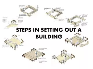
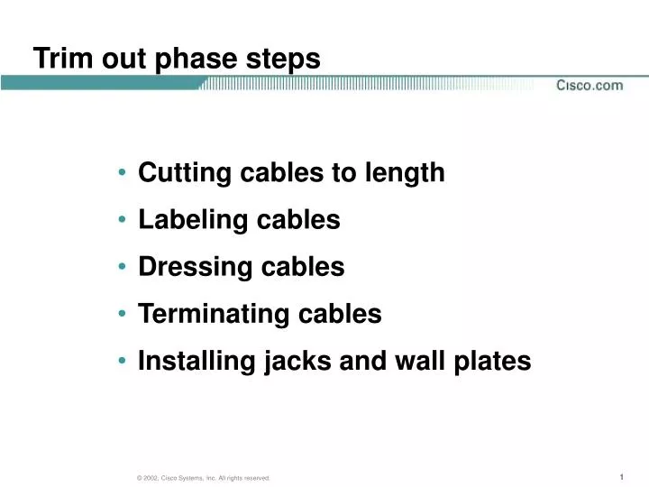
Trim out phase steps. Cutting cables to length Labeling cables Dressing cables Terminating cables Installing jacks and wall plates. Cutting cable.

E N D
Trim out phase steps • Cutting cables to length • Labeling cables • Dressing cables • Terminating cables • Installing jacks and wall plates
Cutting cable • When cutting cable, leave excess cable to allow for mistakes or problems when terminating at the patch and termination panels in the telecommunications rooms. • At the wall outlet, leave some excess cable that can be coiled in the wall box.
Labeling cable • Labeling cable is essential to good cable management. • It is best to label cable before terminating it. If this was not done, use a tone and probe set to identify the cables. • Use an industry accepted labeling scheme such as the one specified in ANSI/TIA/EIA 606.
Dressing cables • Cable management is important to protect and organize cables. • It is never acceptable to place cables over a dropped ceiling or to lay them on ceiling tiles. • Similarly, cables should not be exposed around work areas since they can be accidentally stretched, kicked, or even pulled out of the outlet.
Types of management equipment • Raceways • Baskets • J-hooks and bridle rings • D-rings and mushrooms • Ladder systems • Cable trays • Fasteners • Management systems
Management systems • Cables management systems can be open or closed. • Open systems are accessible so it is easy to route, test, add, or remove cables. • Closed systems provide better protection for the cables from dust, water, rodents, and insects.
Management system qualities • The system should protect the cable from pinching and maintain the maximum bend radius. • The system is scalable so when more cables are needed, it can handle them. • The system is flexible so cables can come into it from all directions. • The system offers a smooth transition to horizontal pathways so cable is not damaged or exceeds maximum bend radius. • The system is durable so that it will last as long as the cables and equipment that is mounted on it.
Terminating media • When cable is run between a TR and a work area • One end is terminated on a patch panel in the TR • The other end is terminated at the work area outlet.
Terminating on patch panels • Patch panels are used to interconnect data networking or voice systems to the physical cable network. • Patch panels are also used to interconnect backbone cable systems to network distribution cable systems. • A uniform wiring plan must be used throughout a patch panel system. All jacks and patch panels should be wired using the same wiring plan.
Patch panels • The rear of the patch panel has network cables that are punched down. • The front of the patch panel has a factory-terminated interface of some type into which patch cords are inserted.
Patching • Patching is the term used when connecting two devices with pre-fabricated patch cords.
Cross-connecting • Cross-connecting is the term used for the interconnection of networks or the connection of information outlets or jacks to network equipment. • Cross-connect wire is punched down directly on the punch down termination panels rather than using a patch cord.
Terminating copper media There are many types of connectors used to terminate copper media: • RJ-45 for Category 5, 5e, and 6 • RJ-11 for Category 3 • RJ-48 for T-1 lines • BNC and F-type for coaxial cabl • STP-A for STP cable • Connectors for termination blocks
RJ-45 wiring schemes • TIA/EIA T568A or T568B wiring scheme should be used for all RJ-45 plugs and jacks. In retrofit projects, use the existing scheme. • In North America, the most common wiring scheme for networks is T568B. T568A is generally only used by its creator – AT&T.
Terminating fiber-optic media • Fiber-optic terminations require special and sometimes expensive equipment, specialized training, and considerably more time than copper. • The ends must be cleanly cut and scratch-free.
TIA/EIA 598A wiring scheme • The wiring scheme for fiber-optic cable is specified in TIA/EI 598A. • Try Ring color mnemonics, followed Tip color mnemonics, followed by “Racing Attention”
Color coded fiber-optic cables • Fiber-optic cables can be identified by the color of the jacket. • Single-mode cables, used for jumpers or patch cords, are yellow. • Multimode cables are orange.
Fiber-optic jumper and patch cables • Fiber-optic jumpers are used to interconnect equipment. • Fiber-optic patch cables are used for connecting one cable to another.
Fiber-optic connectors • SC Reference Slide • ST Reference Slide • FC Reference Slide • MT-RJ, LC, MTP • Reference Slide
Fiber-optic splicing • Splicing is joining two pieces of fiber-optic cable. • There are two methods used to splice fiber-optic cable: mechanical and fusion.
Mechanical splicing • The mechanical splice connector provides precision alignment so that the cores of the two fibers are aligned as close to one another as physically possible. Any misalignment, no matter how small, will increase attenuation or loss of signal. • Less expensive option to fusion splicing.
Fusion splicing • Fusion splicing is the actual welding of the optical fibers to one another. • Light is injected into one of the fibers. The other fiber is adjusted until the strongest beam of light is received in the other fiber. Then the fibers are fused together. • More expensive yet more precise.