Download
1 / 27
270 likes | 281 Views
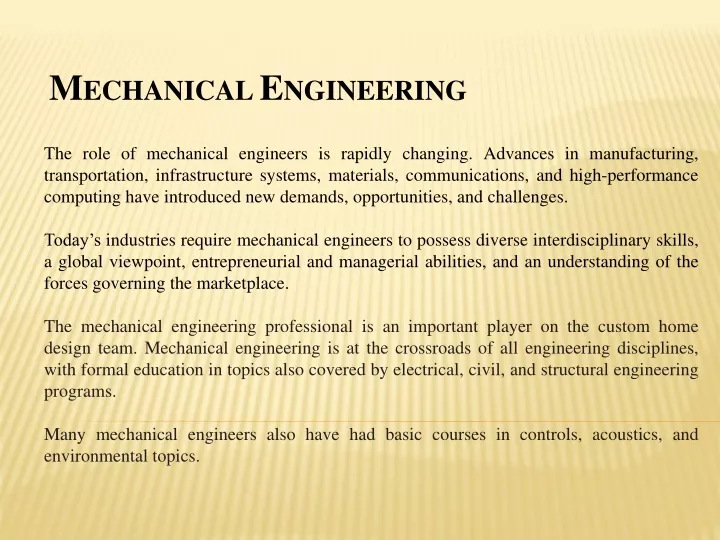
M ECHANICAL E NGINEERING The role of mechanical engineers is rapidly changing. Advances in manufacturing, transportation, infrastructure systems, materials, communications, and high-performance computing have introduced new demands, opportunities, and challenges.

E N D
MECHANICAL ENGINEERING The role of mechanical engineers is rapidly changing. Advances in manufacturing, transportation, infrastructure systems, materials, communications, and high-performance computing have introduced new demands, opportunities, and challenges. Today’s industries require mechanical engineers to possess diverse interdisciplinary skills, a global viewpoint, entrepreneurial and managerial abilities, and an understanding of the forces governing the marketplace. The mechanical engineering professional is an important player on the custom home design team. Mechanical engineering is at the crossroads of all engineering disciplines, with formal education in topics also covered by electrical, civil, and structural engineering programs. Many mechanical engineers also have had basic courses in controls, acoustics, and environmental topics.
Introduction • Metal cutting operations • Manually – by using hand tools such as chisels, files etc. • Machines - machine tools • Machine tools • A machine tool may be defined as a power driven machine which accomplishes the cutting operations • The fundamental machine tools that are used for most of the machining operations are lathe, drilling, tapping, milling, grinding machines.
LATHE • Lathe is a machine tool employed generally to produce cylindrical objects. • It is said to be mother of all the machine tools. • Types of lathe • Engine lathe • Speed lathe • Turret lathe • Capstan lathe • CNC lathe
Engine lathe • Is the most commonly used general purpose lathe used in engineering workshops • Principle of working
Bed • The bed is the main component of a lathe. • All the major components are mounted on the lathe bed, like tail stock, headstock, carriage, etc. Tailstock and carriage move over the guide ways provided on top face of the bed. • The bed material should have high compressive strength and high wear resistance. Cast iron alloyed with nickel chromium forms a good material for bed.
Headstock • Headstock is mounted on the left hand side of the lathe bed. • The head stock accommodates gear box, which helps to vary the spindle speed. The gear box also transmits the power to other parts like feed rod and lead screw. • The chuck or face plate is attached to the spindle which provides mechanical means clutching and rotating the work piece. • Head stock is also known as live center
Tailstock • The tailstock is mounted on the right hand side of the lathe bed. • The function of the tailstock is to support the work piece, and to accommodate different tools like drill, reaming, boring and tapping, etc. • The tailstock moves on the guide ways over the bed, to accommodate for different length of work piece. • Tailstock is known as dead center.
Carriage • The carriage is mounted on the lathe bed, which slides on the guide ways of the bed. • The carriage has various other parts like, cross slide, compound rest, and tool post.
Saddle • The saddle is mounted on the bed and slides along the ways. • The cross slide and tool post are mounted on the saddle. • The movement of the saddle is parallel along the axis of the lathe, it is also known as feed.
Cross slide • The cross slide is mounted on the top of the saddle. This moves the tool at perpendicular to the work piece or machine axis. • The cross slide can be moved either by rotating the cross slide hand wheel. • The perpendicular distance moved by the cross slide is proportional to the amount of metal removed and it is known as depth of cut.
Compound slide • The compound slide (compound rest) is mounted on the top of the cross slide. • Compound slide is used to obtain taper on the work piece.
Tool post • The tool post is mounted on top of the compound slide. • The tool post holds the tool rigidly.
Feed rod • Feed rod is a long shaft extending from the feed box. • The power is transmitted from a set of gears from headstock. • The feed rod is used to move the carriage or cross slide for turning, boring and facing operations.
Lead screw • The lead screw is a long threaded shaft connected to the headstock. • The lead screw is used only when thread cutting operation is to be carried out on the work piece. • For normal turning operations the lead screw is disengaged.
Lathe Operations • Different types of operations that can be carried out • Facing • Straight Turning • Chamfering • Knurling • Grooving and parting off • Drilling • Boring • Taper turning • Thread cutting
Facing • Facing is the process of removing metal from the end of a work piece to produce a flat surface. • The work piece rotates about its axis and the facing tool is fed perpendicular to the axis of lathe.
Straight Turning • Turning is the removal of metal from the outer diameter of a rotating cylindrical work piece. • Turning is used to reduce the diameter of the work piece, usually to a specified dimension.
Chamfering • It is a process of creating a slope at the end of the work piece. • This process is carried out for removing the unwanted metals and burrs after turning operation.
Knurling • Knurling is the process of embossing a required shaped pattern on the surface of the work piece. • This diagram shows the knurling tool pressed against a piece of circular work piece.
Parting • Parting off is the operation of cutting a work piece after it has been finished to the desired dimension and shape. • In parting operation both feed is fixed or locked and depth of cut is controlled properly until the work is cut off in parts.
Taper turning • A taper may be defined as a uniform decrease in diameter of work piece measured along its length. • Taper surface is generated on a cylindrical work piece. • The amount of taper in a work piece is usually specified by the difference in diameters of the taper to its length. • D-Large diameter of taper in mm. • d- Small diameter of taper in mm. • l- Length of tapered part in mm. • α- Angle of taper or half taper angle.
Thread Cutting • Thread cutting is the operation of producing helical groove on a cylindrical surface. • Threads may be square or v threads can be cut on a cylindrical work piece. • The threads of any pitch, shape and size can be cut on a lathe. • A single point cutting tool (V-tool or square tool) is used to cut threads on the work piece.
Thread Cutting • For thread cutting operation, the tool is moved automatically in longitudinal direction. • The longitudinal feed should be equal to the pitch of the thread to be cut per revolution of the work.
Specification of a Lathe 1.)The length of the bed, 2) The distance between the centers. 3)The swing diameter of work over bed, 4)The swing diameter of work over the carriage, 5) Power input 6)Lead screw details, 7) Number of spindle speeds 8) Feeds, 9) Width of bed