Download
1 / 24
240 likes | 463 Views
Unit 7 Sitecast Concrete. Part ⅠIllustrated Words and Concepts Figure 7-1 The Construction of a Concrete Slab on Grade Figure 7-2 Section through a Reinforced Concrete Wall

E N D
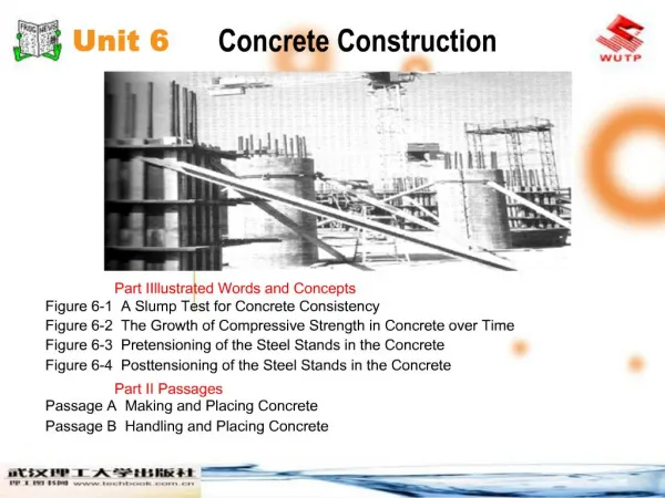
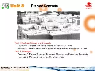
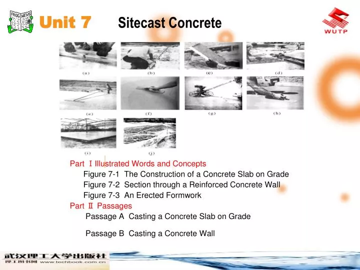
Unit 7 Sitecast Concrete Part ⅠIllustrated Words and Concepts Figure 7-1 The Construction of a Concrete Slab on Grade Figure 7-2 Section through a Reinforced Concrete Wall Figure 7-3 An Erected Formwork Part Ⅱ Passages Passage A Casting a Concrete Slab on Grade Passage B Casting a Concrete Wall
Unit 7 Sitecast Concrete Part Ⅰ Illustrated Words and Concepts Figure 7-1 The Construction of a Concrete Slab on Grade Notice how the wire reinforcing fabric is overlapped where two sheets of fabric join.
Unit 7 Sitecast Concrete Part Ⅰ Illustrated Words and Concepts Figure 7-2 Section through a Reinforced Concrete Wall Section through a reinforced concrete wall, with two layers of horizontal and vertical reinforcing bars for greater strength.
Unit 7 Sitecast Concrete Part Ⅰ Illustrated Words and Concepts Figure 7-3 An Erected Formwork The formwork is erected. Sheet of plywood form the face of the concrete. They are supported by vertical wood studs. The studs are supported against the pressure of the wet concrete by horizontal walers. The walers are supported by steel rod ties that pass through holes in the plywood to the walers on the other side. The ties also act as spreaders to maintain a spacing between the plywood walls that is equal to the desired thickness of the wall. Diagonal braces keep the whole assembly plumb and straight.
Unit 7 Sitecast Concrete Part ⅡPassagesPassage A Casting a Concrete Slab on Grade Casting a Concrete Slab on Grade A concrete slab on grade is a level surface of concrete that lies directly on the ground. Slabs on grade are used for roads, sidewalks, patios , airport runways, and ground floors of buildings. A slab-on-grade floor usually experiences little structural stress except a direct transmission of compression between its superimposed loads and the ground beneath,
Unit 7 Sitecast Concrete Part ⅡPassagesPassage A so it furnishes a simple example of the operations involved in the sitecasting of concrete. (see Figure 7 1). To prepare for the placement of a slab on grade, the unstable topsoil is scraped away to expose the subsoil beneath. A layer of 3/4inchdiameter (19mm) crushed stone at least 4 inches (100 mm) deep is compacted over the subsoil as a drainage layer to keep water away from the underside of the slab.
Unit 7 Sitecast Concrete Part ⅡPassagesPassage A A simple edge form—a strip of wood or metal fastened to stakes driven into the ground—is constructed around the perimeter of the area to be poured and is coated with a form release compound to prevent the concrete from sticking. (see cover picture) The top edge of the form is carefully leveled.
Unit 7 Sitecast Concrete Part ⅡPassagesPassage A The thickness of the slab may range from 3 inches (100 mm) for a residential floor to 6 or 8 inches (150 or 200 mm) for an industrial floor. If the slab is to be the floor of a building, a moisture barrier (usually a heavy sheet of polyethylene plastic ) is laid over the crushed stone to prevent water from rising through the slab from the ground beneath.
Unit 7 Sitecast Concrete Part ⅡPassagesPassage A A reinforcing mesh of welded wire fabric, cut to a size just a bit smaller than the dimensions of the slab, is laid over the moisture barrier or crushed stone. For slabs in factories, warehouses, and airports, a fabric made of heavier wires or a grid of reinforcing bars may be used instead. The grid of wires or bars helps protect the slab against cracking that might be caused by concrete shrinkage, temperature stresses,
Unit 7 Sitecast Concrete Part ⅡPassagesPassage A concentrated loads, frost heaving, or settlement of the ground beneath. Fibrous admixtures are finding increasing acceptance as a means of controlling the plastic shrinkage cracking that often takes place during curing of a slab. Fibrous reinforcing, however, is not strong enough to replace wire fabric for general crack control in slabs. Control joints must be provided at intervals in a slab on grade.
Unit 7 Sitecast Concrete Part ⅡPassagesPassage A A control joint is a straight, intentional crack that is formed before the concrete has hardened fully. The function of a control joint is to provide a place where the forces that cause cracking can be relieved without disfiguring the slab. A control joint may be created by inserting a fibrous strip into the form before the slab is poured. It may also be made by other methods.
Unit 7 Sitecast Concrete Part ⅡPassagesPassage A Pouring and Finishing the Slab on Grade Pouring (casting) of the slab commences with the placing of concrete into the formwork. This may be done directly from the chute of a transit-mix truck, or with wheelbarrows, concrete buggies, a large crane-mounted concrete bucket, a conveyor belt, or a concrete pump and hoses. The method selected will depend on the scale of the job and the accessibility of the slab to the truck delivering the concrete.
Unit 7 Sitecast Concrete Part ⅡPassagesPassage A The concrete is spread by workers using shovels or rakes until the form is full. Then the same tools are used to agitate the concrete slightly, especially around the edges, to eliminate air pockets. Next, the concrete masons reach into the wet concrete with metal hooks and raise the welded wire fabric to the mid-height of the slab, so that it will be able to resist tensile forces caused by forces acting either upward or downward.
Unit 7 Sitecast Concrete Part ⅡPassagesPassage A If a smoother surface is desired, the slab is next floated.The masons wait until the watery sheen has evaporated from the surface of the slab, then smooth the concrete with a flat tool called a float. As the float is drawn across the surface, the friction generated by this roughness vibrates the concrete gently and brings cement paste to the surface, where it is smoothed over the coarse aggregate and into low spots by the float.
Unit 7 Sitecast Concrete Part ⅡPassagesPassage A For a completely smooth, dense surface, the slab must also be troweled. Troweling is done several hours after floating, when the slab is becoming quite firm. It is done either by hand, using a smooth, rectangular steel trowel, or with a rotary power trowel.
Unit 7 Sitecast Concrete Part ⅡPassagesPassage A When the finishing operations have been completed, the slab should be cured under damp conditions for at least a week; otherwise, its surface may crack or become dusty from premature drying. Damp curing may be accomplished by covering the slab with an absorbent material such as sawdust, earth, sand, straw, or burlap, and maintaining the material in a damp condition for the required time.
Unit 7 Sitecast Concrete Part ⅡPassagesPassage B Casting a Concrete Wall A reinforced concrete wall at ground level usually rests on a poured concrete strip footing. The footing is formed and poured much like a concrete slab on grade. Its cross-sectional dimension and its reinforcing, if any, are determined by the structural engineer. A key, a groove that will form a mechanical connection to the wall, is sometimes formed in the top of the footing with strips of wood that are temporarily embedded in the wet concrete.
Unit 7 Sitecast Concrete Part ⅡPassagesPassage B Vertically projecting dowels of steel reinforcing bars are usually installed in the footing before pouring; these will later be overlapped with the vertical bars in the walls to form a strong structural connection. After pouring, the top of the footing is straightedged; no further finishing operations are required. The footing is left to cure for at least a day before the wall forms are erected.
Unit 7 Sitecast Concrete Part ⅡPassagesPassage B The wall reinforcing, either in one vertical layer of horizontal and vertical bars at the center of the wall or two vertical layers near the faces of the wall, as specified by the structural engineer, is installed next, with the bars wired to one another at the intersections. The vertical bars are overlapped with the corresponding dowels projecting from the footing.
Unit 7 Sitecast Concrete Part ⅡPassagesPassage B L-shaped horizontal bars are installed at wall corners to maintain full structural continuity between the two walls. If the top of the wall will connect to a concrete floor or another wall, rods are left projecting from the formwork. These will be embedded in the later pour of concrete to form a continuous connection.
Unit 7 Sitecast Concrete Part ⅡPassagesPassage B When the ties are in place and the reinforcing has been inspected, the formwork for the second side of the wall is erected, the walers and braces are added, and the forms are inspected to be sure that they are straight, plumb, correctly aligned, and adequately tied and braced. A surveyor’s transit is used to establish the exact height to which the concrete will be poured and this height is marked all around the inside of the forms. Pouring may then proceed.
Unit 7 Sitecast Concrete Part ⅡPassagesPassage B Concrete is brought to the site, test cylinders are made, and a slump test is performed to check for the proper pouring consistency . Concrete is then transported to the top of the wall by a large crane-mounted bucket or by a concrete pump and hose. Workers standing on planks at the tops of the forms deposit the concrete in the forms,
Unit 7 Sitecast Concrete Part ⅡPassagesPassage B consolidating it with a vibrator to eliminate air pockets. When the form has been filled and consolidated up to the level that was marked inside the formwork, hand floats are used to smooth and level the top of the wall. The top of the form is then covered with a plastic sheet or canvas, and the wall is left to cure.
Unit 7 Sitecast Concrete Part Ⅱ PassagesPassage B After a few days of curing, the bracing and walers are taken down, the connectors are removed from the ends of the form ties, and the formwork is stripped from the wall. This leaves the wall bristling with projecting ends of form ties. These are twisted off with heavy pliers , and the holes that they leave in the surfaces of the wall are carefully filled with grout. If required, major defects in the wall surface caused by defects in the formwork or inadequate filling of the forms with concrete can be repaired at this time. The wall is now complete.