Download
1 / 51
520 likes | 769 Views
Review of lattice design for low emittance ring. R. Bartolini Diamond Light Source Ltd and John Adams Institute, Dept. of Physics, University of Oxford. Low Emittance Rings Workshop, Crete 3 rd October 2011. Luminosity and brilliance scale together. Motivations.

E N D
Review of lattice design for low emittance ring R. Bartolini Diamond Light Source Ltd and John Adams Institute, Dept. of Physics, University of Oxford Low Emittance Rings Workshop, Crete 3rd October 2011
Luminosity and brilliance scale together Motivations both increase with smaller emittances both increase with higher current (…within limits beam-beam, collective effects, diffraction, etc) and damping rings are required to generate small emittance beams for colliders Low Emittance Rings Workshop, Crete 3rd October 2011
Light sources diffraction limited operation at 0.1nm requires 10’s pm Motivations Colliders (B-factories) 1036 cm-2 s-1 requires 2nm (5nm for superKEKB) as present state-of-the-art light sources Damping rings 500 pm H and 2 pm V (specs for ILC-DR) <100 pm H and 5 pm V (specs for CLIC-DR) Low Emittance Rings Workshop, Crete 3rd October 2011
This workshop’s programme ! Low emittance lattice solutions dynamic aperture and momentum aperture low emittance tuning Collective effects IBS e-cloud fast-ion, RW, CSR and others Advanced technology Damping wigglers - In-vacuum IDs high resolution BPMs optical diagnostics (laser wire, pinholes, etc) high vacuum (NEG coating and low SEY material) Injection schemes (time structure for DR and DA for light sources) this talk Accelerator physics and technology challenges see R. Nagaoka’s talk see E. Wallen’s talk Low Emittance Rings Workshop, Crete 3rd October 2011
Emittance in 3rd GLS, DR and colliders Low Emittance Rings Workshop, Crete 3rd October 2011
Design challenges • Low emittancelatticesfor light sources • Low emittancelatticesfordampingrings • motivations • design approaches • tools • predicted performance Low Emittance Rings Workshop, Crete 3rd October 2011
3rd generation storage ring light sources 1992ESRF, France (EU) 6 GeV ALS, US 1.5-1.9 GeV 1993 TLS, Taiwan 1.5 GeV 1994ELETTRA, Italy 2.4 GeV PLS, Korea 2 GeV MAX II, Sweden 1.5 GeV 1996APS, US 7 GeV LNLS, Brazil 1.35 GeV 1997 Spring-8, Japan 8 GeV 1998BESSY II, Germany 1.9 GeV 2000ANKA, Germany 2.5 GeV SLS, Switzerland 2.4 GeV 2004SPEAR3, US 3 GeV CLS, Canada 2.9 GeV 2006: SOLEIL, France 2.8 GeV DIAMOND,UK 3 GeV ASP, Australia 3 GeV MAX III, Sweden 700 MeV Indus-II, India 2.5 GeV 2008SSRF, China3.4 GeV 2009PETRA-III, Germany 6 GeV 2011ALBA, Spain 3 GeV ESRF Diamond
3rd generation storage ring light sources under construction or planned NLSL-II > 2011NSLS-II, US 3 GeV MAX-IV, Sweden 1.5-3 GeV SOLARIS, Poland 3 GeV SESAME, Jordan 2.5 GeV TPS, Taiwan3 GeV CANDLE, Armenia 3 GeV PEP-X, USA 4.5 GeV Spring8-II, Japan 6 GeV Max-IV Low Emittance Rings Workshop, Crete 3rd October 2011
3rd generation storage ring light sources Low Emittance Rings Workshop, Crete 3rd October 2011
Users’ requirements and Acc. Phys. and technology challenges Photon energy Flux Brilliance Stability Polarisation Time structure Ring energy Small Emittance Insertion Devices High Current; Feedbacks Vibrations; Orbit Feedbacks; Top-Up Short bunches; Short pulses Low Emittance Rings Workshop, Crete 3rd October 2011
Brilliance with IDs (medium energy light sources) Medium energy storage rings with in-vacuum undulators operated at low gaps (e.g. 5-7 mm) can reach 10 keV with a brilliance of 1020 ph/s/0.1%BW/mm2/mrad2 Low Emittance Rings Workshop, Crete 3rd October 2011
Brilliance with IDs (ESRF upgrade) Brilliance gain on the ESRF upgrade driven by higher stored current and smaller vertical emittance Low Emittance Rings Workshop, Crete 3rd October 2011
Low emittance lattices Lattice design has to provide low emittanceandadequate space in many straight sections to accommodate long Insertion Devices Minimise and D and be close to a waist in the dipole Zero dispersion in the straight section was used especially in early machines avoid increasing the beam size due to energy spread hide energy fluctuation to the users allow straight section with zero dispersion to place RF and injection decouple chromatic and harmonic sextupoles DBA and TBA lattices provide low emittance with large ratio between Flexibility for optic control for apertures (injection and lifetime)
3rd generation storage ring LS and damping rings Lattice Design: DBA, TBA, Multi-Bend Lattice, TME-Structure controlled dispersion in straight sections Radiation Excitation and Damping Manipulations: Damping Wiggler : PETRA-III, NSLS-II, MAX IV, PEP-X, Damping Rings Combined B (Partition Control) Robinson Wiggler (Partition Control) see L. Nadolski’s talk Longitudinally Variable B (Optimized Radiation Integral) see C. Wang’s talk Low Emittance Rings Workshop, Crete 3rd October 2011
APS ALS DBA and TBA Double Bend Achromat (DBA) Triple Bend Achromat (TBA) DBA used at: ESRF, ELETTRA, APS, SPring8, Bessy-II, Diamond, SOLEIL, SPEAR3 ... TBA used at ALS, SLS, PLS, TLS …
Breaking the achromatic condition Leaking dispersion in straight sections reduces the emittance ESRF 7 nm 3.8 nm APS 7.5 nm 2.5 nm SPring8 4.8 nm 3.0 nm SPEAR3 18.0 nm 9.8 nm ALS (SB) 10.5 nm 6.7 nm APS The emittance is reduced but the dispersion in the straight section increases the beam size ASP Need to make sure the effective emittance and ID effects are not made worse
Low emittance lattices MAX-IV New designs envisaged to achieve sub-nm emittance involve Damping Wigglers Petra-III: 1 nm NSLS-II: 0.5 nm MBA MAX-IV (7-BA): 0.5 nm Spring-8 (10-BA): 83 pm (2006) 10-BA had a DA –6.5 mm +9 mm reverted to a QBA (160 pm) now 6BA with 70 pm see K. Soutome’s talk Spring-8 upgrade
Max-IV 20-fold 7-BA achromat Max-IVstudiesprovedthat a 7-BA (330 pm, and 260 pm with DW) can deliversuffcient DA and MA to operate with standard injectionschemes Toolsused FM – drivingterms Additionaloctupoleswerefoundtobeeffective Courtesy S. Leemans
PEP-X 7 bend achromat cell Natural emittance = 29 pm-rad at 4.5 GeV 5 TME units Cell phase advances: mx=(2+1/8) x 3600, my=(1+1/8) x 3600. Courtesy B. Hettel Low Emittance Rings Workshop, Crete 3rd October 2011
Reduced emittance with damping wigglers Emittance = 11 pm-rad at 4.5 GeVwith parameters lw=5 cm, Bw=1.5 T Wiggler Field Optimization Wiggler Length Optimization Average beta function at the wiggler section is 12.4 meter. Courtesy Min-Huey Wang, B. Hettel, Y. Cai Low Emittance Rings Workshop, Crete 3rd October 2011
Cancellation of resonances All Geometrical 3rd and 4th Resonances Driven by Strong Sextupoles except 2nx-2ny Third Order Fourth Order Courtesy Min-Huey Wang, B. Hettel, Y. Cai Low Emittance Rings Workshop, Crete 3rd October 2011
Additional sextupoles for tuneshift and 2nx-2ny Without Harmonic Sextupoles With Harmonic Sextupoles Optimized with OPA (Accelerator Design Program from SLS PSI). Courtesy Min-Huey Wang, B. Hettel, Y. Cai Low Emittance Rings Workshop, Crete 3rd October 2011
Optimisation with parallel computing and ELEGANT Dynamic Aperture at Injection • Excellent design of an ultimate storage ring for PEP-X • Approaching diffraction limit at one angstrom • Reasonable beam current 200 mA • Good beam lifetime 3 hours • Good injection with 10 mm acceptance • Achievable machine tolerances Low Emittance Rings Workshop, Crete 3rd October 2011 Courtesy Min-Huey Wang, B. Hettel, Y. Cai
New ILC Damping Ring Baseline Lattice Usually damping rings lattices have a racetrack layout with long straight sections including RF cavities, injection, extraction and long wiggler sections Courtesy S. Guiducci Low Emittance Rings Workshop, Crete 3rd October 2011
DR for linear collider lattices DR lattices are wiggler dominated: Wigglers are needed to achieve the required damping time Emittance with wigglers U0 = Uarc + Uwig = Uarc (1 + Fw) ex = ea/(1+Fw) + ew Fw/(1+Fw) For linear collider damping rings: ew << ea ; Fw>>1 ex ~ ea/Fw Courtesy S. Guiducci Low Emittance Rings Workshop, Crete 3rd October 2011
3.2 km Damping Ring - Lattice Comparison DTC01, TME-style DSB3, SuperB-style DMC3, FODO All the arc cell styles satisfy emittance and damping time requirements. S. Guiducci, M. E. Biagini, “A Low Emittance Lattice for The ILC 3 Km Damping Ring”, IPAC’10 D. Wang, J. Gao, Y. Wang, “A New Design for ILC 3.2 km Damping Ring Based on FODO Cell”, IPAC’10 D. Rubin, DR TBR, LNF July 2011, http://ilcagenda.linearcollider.org/conferenceDisplay.py?confId=5183 S. Guiducci et al., , “Updates to the International Linear Collider Damping Rings Baseline Design”, IPAC’11
3.2 km ILC damping ringmain parameters comparison Courtesy S. Guiducci Low Emittance Rings Workshop, Crete 3rd October 2011
ILC-CLIC Damping Ring comparisons M.Korostelev, A.Wolski, “DCO4 Lattice Design For 6.4 Km ILC Damping Rings”, IPAC’10 Y. Papaphilippou et al., , “Lattice Options for the CLIC Damping Rings”, IPAC’09 Courtesy S. Guiducci
ILC Damping Ring Dynamic Aperture DTC01 For ILC damping ring the DA has to be 3sx of the “large” positron beam, which is 130sx of the stored beam Courtesy S. Guiducci Low Emittance Rings Workshop, Crete 3rd October 2011
Non-linear optics optimisation and control with low emittance lattices Low emittance Large Nat. Chromaticity with Strong quads and Small Dispersion Strong SX Small Apertures (Dynamic and Momentum apertures) Usually the phase advance per cell is such that low resonance driving terms are automatically compensated (to first order) Numerical optimisation is however unavoidable need 6D tracking (watch out alpha_2) use DA and FM plots use MOGA ! MOGA in elegant to optimise 8 sextupole families at Diamond improved the Touschek lifetime by 20 % Low Emittance Rings Workshop, Crete 3rd October 2011
MOGA DA studies for NSLS-II NLSL-II lattice = 0.55 nm with damping wigglers with 3 damping wigglers Tracked DA directly used as objective as area of ellipses for different dp/p and-or detuning with amplitude Low Emittance Rings Workshop, Crete 3rd October 2011
Operational challenges • Implementationof the linearopticsof low emittancelattices • beta beating • linearcoupling • Low emittancetuning • Implementationof the non-linearoptics • FrequencyMapAnalysis • Drivingterms Low Emittance Rings Workshop, Crete 3rd October 2011
Oxford 15 miles Light sources optics controls Diamond is a third generation light source open for users since January 2007 2.7 nm emittance – 18 beamlines in operation (10 in-vacuum small gap IDs) Most state-of-the-art light sources share the same structure
Energy 3 GeV Circumference 561.6 m No. cells 24 Symmetry 6 Straight sections 6 x 8m, 18 x 5m Insertion devices 4 x 8m, 18 x 5m Beam current 300 mA (500 mA) Emittance (h, v) 2.7, 0.03 nm rad Lifetime > 10 h Min. ID gap7 mm (5 mm) Beam size (h, v)123, 6.4 mm Beam divergence (h, v)24, 4.2 mrad (at centre of 5 m ID) Beam size (h, v)178, 12.6 mm Beam divergence (h, v)16, 2.2 mrad (at centre of 8 m ID) Diamond storage ring main parametersnon-zero dispersion lattice 48 Dipoles; 240 Quadrupoles; 168 Sextupoles (+ H and V orbit correctors + 96 Skew Quadrupoles) 3 SC RF cavities; 168 BPMs Quads + Sexts have independent power supplies
Hor. - beating Ver. - beating Quadrupole gradient variation Linear optics modelling with LOCOLinear Optics from Closed Orbit response matrix – J. Safranek et al. Modified version of LOCO with constraints on gradient variations (see ICFA Newsl, Dec’07) - beating reduced to 0.4% rms Quadrupole variation reduced to 2% Results compatible with mag. meas. and calibrations LOCO allowed remarkable progress with the correct implementation of the linear optics
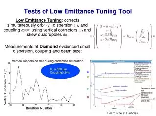
Measured emittances Coupling without skew quadrupoles off K = 0.9% (at the pinhole location; numerical simulation gave an average emittance coupling 1.5% ± 1.0 %) Emittance [2.78 - 2.74] (2.75) nm Energy spread [1.1e-3 - 1.0-e3] (1.0e-3) After coupling correction with LOCO (2*3 iterations) 1st correction K = 0.15% 2nd correction K = 0.08% V beam size at source point 6 μm Emittance coupling 0.08% → V emittance 2.2 pm Variation of less than 20% over different measurements
Comparison machine/model andLowest vertical emittance * best achieved
Last year results on low emittance tuning and the achievement of a vertical emittance of 2.0 pm at Diamond and SLS have sparked quite some interest from the Damping ring community (CLIC and ILC) and from the Super B In collaboration with the SuperB team (P. Raimondi,. M. Biagini, S: Liuzzo) Diamond and SLS have been used as a test-bed for new techniques for low emittance tuning based on dispersion free steering and coupling free steering. Low emittance tuning at Diamond and SLS for SuperB 4 MD shifts at DLS November 10 - February 11 See S. Liuzzo’s talk
State-of-the-art light sourceshave BPMs with turn-by-turn capabilities • e.g. Diamond • excite the beam diagonally • measure tbt data at all BPMs • colour plots of the FFT H BPM number QX = 0.22 H tune in H Qy = 0.36 V tune in V V All the other important lines are linear combination of the tunes Qx and Qy BPM number m Qx + n Qy frequency / revolution frequency Low Emittance Rings Workshop, Crete 3rd October 2011
See A. Franchi’s talk ESRF coupling correction with spectral lines (I) Low Emittance Rings Workshop, Crete 3rd October 2011 Courtesy A. Franchi
ESRF record low emittanceJune 2010 – At ID gaps open 4.4 0.7 pm ESRF coupling correction with spectral lines (II) • Reducedto 3.7 pm withadditioanlskewquadrupoles • Compensationofcouplingduring ID gapsmovement • feedforwardtables: gapstoskewquads via couplingmeasurements • feedback: V emittance – skewquads via C- drivingterms Courtesy A. Franchi Low Emittance Rings Workshop, Crete 3rd October 2011
Spectral line (-1, 1) in V associated with the sextupole resonance (-1,2) Comparison spectral line (-1,1) from tracking data and measured (-1,1) observed at all BPMs Spectral line (-1,1) from tracking data observed at all BPMs model model; measured BPM number BPM number Low Emittance Rings Workshop, Crete 3rd October 2011
Using the measured amplitudes and phases of the spectral lines of the betatron motion we can build a fit procedure to calibrate the nonlinear model of the ring Accelerator Model Accelerator FrequencyAnalysisofBetatronMotion and Lattice ModelReconstruction • tracking data at all BPMs • spectral lines from model (NAFF) • beam data at all BPMs • spectral lines from BPMs signals (NAFF) e.g. targeting more than one line Define the distance between the two vector of Fourier coefficients Least Square Fit of the sextupole gradientsto minimise the distance χ2 of the two Fourier coefficients vectors
Simultaneous fit of (-2,0) in H and (1,-1) in V (-1,1) (-2,0) sextupoles start iteration 1 iteration 2 Both resonance driving terms are decreasing
Sextupole variation Now the sextupole variation is limited to < 5% Both resonances are controlled We measured a slight improvement in the lifetime (10%) Low Emittance Rings Workshop, Crete 3rd October 2011
SOLEIL’s – off momentum FM Simulations Measurements Agreement few% up todp/p 4 % Courtesy L. Nadolski Low Emittance Rings Workshop, Crete 3rd October 2011
Frequency map and detuning with momentum comparisonmachine vs model (I) Using the measured Frequency Map and the measured detuning with momentum we can build a fit procedure to calibrate the nonlinear model of the ring Accelerator Model Accelerator • tracking data • build FM and detuning with momentum • BPMs data with licked beams • measure FM and detuning with momentum The distance between the two vectors can be used for a Least Square Fit of the sextupole gradientsto minimise the distance χ2 of the two vectors
Frequency map and detuning with momentum comparisonmachine vs model (II) detuning with momentum model and measured FM measured FM model Sextupole strengths variation less than 3% The most complete description of the nonlinear model is mandatory ! Measured multipolar errors to dipoles, quadrupoles and sextupoles (up to b10/a9) Correct magnetic lengths of magnetic elements Fringe fields to dipoles and quadrupoles Substantial progress after correcting the frequency response of the Libera BPMs
Frequency map and detuning with momentum comparisonmachine vs model (III) Synchrotron tune vs RF frequency DA measured DA model The fit procedure based on the reconstruction of the measured FM and detuning with momentum describes well the dynamic aperture, the resonances excited and the dependence of the synchrotron tune vs RF frequency R. Bartolini et al. Phys. Rev. ST Accel. Beams 14, 054003 Low Emittance Rings Workshop, Crete 3rd October 2011
Comparison real lattice to modellinear and nonlinear optics Frequency Maps and amplitudes and phases of the spectral line of the betatron motion can be used to compare and correct the real accelerator with the model LOCO Closed Orbit Response Matrix from model fitting quadrupoles, etc Linear lattice correction/calibration Closed Orbit Response Matrix measured R. Bartolini and F. Schmidt in PAC05 Spectral lines + FMA from model fitting sextupoles and higher order multipoles Nonlinear lattice correction/calibration Spectral Lines + FMA measured Combining the complementary information from FM and spectral line should allow the calibration of the nonlinear model and a full control of the nonlinear resonances