Download
1 / 46
550 likes | 839 Views
Layer 2 functionality – bridging and switching. BSAD 141 Dave Novak Sources: Network + Guide to Networks, Dean 2013. Overview. Layer 2 functionality Error detection Bridging Broadcast and collision domains How bridges work Types of bridges Switching Types of switches Buffering.

E N D
Layer 2 functionality – bridging and switching BSAD 141 Dave Novak Sources: Network+ Guide to Networks, Dean 2013
Overview • Layer 2 functionality • Error detection • Bridging • Broadcast and collision domains • How bridges work • Types of bridges • Switching • Types of switches • Buffering
Layer 2 functionality • Unlike layer 1 functionality that simply addresses the transmission of modulated signals over the medium, layer 2 functionality begins to incorporate aspects of network management • Recognition of frame formats • MAC addressing • Some error checking
Layer 2 functionality • Recall from Lecture 2 on the OSI model • NIC is both logical and physical boundary between layers 1 and 2 • Converts bits to frames and vice versa • Error detection in bit to frame conversion • Error detection in media access as access control technique defined at layer 2
Layer 2 Errors • Interference can cause random data to appear or transmitted data to be lost or to be corrupted in some manner • Digital transmission is susceptible to interference • Bits may be altered, lost, or the sequence rearranged, creating errors in the message
Layer 2 Errors • There are three basic data link layer error detection technologies • 1) Parity bits and parity checking • 2) Checksum • 3) Cyclic redundancy check (CRC)
Parity bits and parity checking • Most basic error check • Sending node adds a bit to each character (typically 7 bits / character in RS-232) • Two types of parity • 1) Even • 2) Odd
Parity bits and parity checking • Example: Using EVEN parity – the sender sets the parity bit to either 1 or 0 whichever makes the total number of 1 bits (including parity) even • If character is 0010101, the parity bit is set to ____ • Receiver checks the parity
Checksum • The sender treats data as sequence of binary integers and computes the sum • Receiver checks the sum
Cyclic redundancy check (CRC) • We’ll say this is the most complex layer 2 error checking technique • Software algorithm to determine whether or not data were received correctly • Simple to implement, easy to analyze, and effective in detecting common errors • Does not verify integrity of sender, just correctness • http://en.wikipedia.org/wiki/Cyclic_redundancy_check
Higher Layer Switches • We are discussing layer 2 functionality using specific hardware examples • Distinctions between modern network hardware blurring • Modern networking devices don’t work neatly and exclusively at single layer of OSI • Higher layer switches work at layers 3 (network) and 4 (transport) of OSI • Perform advanced filtering, performance analysis, and security
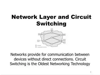
Bridging • Technique used to connect networks at data link layer • Hubs connect networks at ______________ • Adding another hub is analogous to adding more ports to an existing hub or extending a bus topology network • All packets forwarded to all devices on network • No management capabilities
Bridging • A bridge is a physical device • Computer with two NICs • Special device with two ports
Bridging • Incorporates concept of basic management via frame filtering • If LAN segment is congested • Break LAN into 2 segments and bridge them together
Frame/Packet filtering • Read MAC source and destination address of all frames • Can’t go any higher in OSI • Can’t read data in payload • Bridge discards frame and does not forward if receiver is located on same segment as sender • Bridge copies frame and forwards it to the appropriate segment if receiver is on separate segment
Bridges and concept of collision domain • Collision Domain • Add hub to LAN • Add device to port on existing hub • Separate segments of a bridged LAN form two separate collision domains • Improve performance by reducing collisions
Bridges and concept of broadcast domain • Broadcast Domain • Unicast • Multicast
Bridges and concept of broadcast domain • Standard way to locate device Broadcast message asking for IP address
Bridges and concept of broadcast domain • Bridges do not create separate broadcast domains • Bridge relays broadcasts to both segments of bridged LAN • Important conceptual idea: A shared broadcast domain needed for devices to remain part of same LAN or subnet
Adaptive / Transparent Bridging • Learn locations of computers on different segments • Store information in a table that might contain: MAC address, NetBIOS name, segment ID • Starts with no information in the table • Create table of devices on each segment
Adaptive / Transparent Bridging • Bridge performs 2 calculations when frame arrives • 1) Examine source / destination MAC address and add source address to list • 2) Forward frame if needed
How a bridge works • Bridges learn computer locations quickly • Computers tend to be fairly active • The longer the bridge is run without rebooting, the more efficient the operation • Permits simultaneous use of each segment • Can optimize performance (parallelism)
How a bridge works • To improve performance computers that communicate often should be located on same segment • Why? (think about locality of reference…)
Spanning Tree Algorithm (STA) • Frame forwarding algorithm • If a cycle of bridges/switches is present, broadcast will cycle infinitely (infinite loop) • STA prevents infinite loops • Protocol selects single forwarding path on LAN • Detect circular patterns and modify way devices work together • Routers DO NOT forward broadcasts
Discuss 3 bridging functions • 1) Local Bridge • 2) Translation Bridge • 3) Remote Bridge
Local Bridge • Standard device used to connect network segments of the same type (use the same data link protocols or LAN technology) • For example, Ethernet • Very simple • Does not modify data in headers, just reads the MAC address and either passes the frame on or discards it
Translation Bridge • Device used to connect network segments of different types (use different data link protocols or LAN technology) • For example, Ethernet to token ring • More complicated • Strips frame from packets received from one type LAN segment and repackages them in frame suitable for other LAN segment • Recall frame formats are different depending on the underlying data link protocols (LAN technologies used)
A B C D E F G Translation Bridge Ethernet Frame FDDI Frame A B G C D E F H I A = Preamble (7 B) B = Start of Frame Delimiter (1 B) C = Destination Address (6 B) D = Source Address (6 B) E = Ethertype / length (2 B) F = Data and Pad (46 – 1500 B) G = Frame Check (4 B) A = Preamble (8 B) B = Start Delimiter (1 B) C = Frame Control (1 B) D = Destination Address (6 B) E = Source Address (6 B) F = Data (variable) G = Frame Check (4 B) H = End Delimiter (4 b) I = End of Frame Sequence (12 b)
Remote Bridge • Device used to connect network segments at distant locations using some type of WAN link • For example, connect two remote Ethernet segments using a leased telephone line • Could function as either local or translation bridge, but main purpose is to limit traffic on WAN link
Switching • Data link functionality fundamental to most LANs • Replaces a bridge in modern switched Ethernet networking • Allow multiple users to exchange information simultaneously without slowing each other down • Promotes parallelism
Switching • Allow different nodes to communicate directly with each other • Physically resembles a hub • Important conceptual issue: • Hub simulates shared media • Switch simulates a bridged LAN with one computer per segment
Switching • Forward data out a single port • How is this different from a hub ?
Switching • Functionally converts a shared network medium to a dedicated network medium • Creates a separate collision domain for two devices communicating along a dedicated path • Forward broadcasts to all ports • Do NOT forward multicast or unicast to all ports • No device receives packets destined for other systems
Legacy Ethernet (Hub example) Before switching, Ethernet supported only half duplex transmission Hub forwards electrical signals on all ports, so only one PC can use the media at a time – each PC communicates directly with all other PCs on the network. The hub is just a conduit that links the PCs together. PC 4 sends a message destined for PC 3, the hub forwards the packets out all ports, effectively tying up the media and preventing simultaneous (full duplex) communication PC 3 will receive the frames, read the MAC address and “accept” the message All other PCs will also receive the frames, read the MAC address and discard the message PC 1 PC 2 PC 3 Hub PC 4 PC 5 PC 6
Switched Ethernet (Switch example) With switching, Ethernet supports full duplex transmission Each PC communicates directly with the switch, as opposed to directly with the other PCs on the LAN. Information can travel from node to switch and from switch to node simultaneously. PC 4 sends a message destined for PC 3 to the switch. At the same time, PC 2 can send message destined for PC 3 to the switch. The switch will only forward the messages out the port connected directly to PC 3. PC 3 could be communicating with other PCs at the same time Switches provide a collision free environment. Each PC has a dedicated connection to itself PC 1 PC 2 PC 3 Switch PC 4 PC 5 PC 6
Simplified switch example E3-21-OK-8P-00-0C How it works The switch contains a lookup table that maps the MAC address to a specific output port PC 1 PC 2 PC 3 Port 2 Port 1 Ports 1, 2, 3 Switch Ports 4, 5, 6 Port 4 The switch “knows” A6-43-IK-0P-00-12 (PC4) is attached to Port 4. If PC4 is sending a message to E3-21-OK-8P-00-0C (PC1), the switch knows the message must be sent out Port 1 PC 4 PC 5 PC 6 A6-43-IK-0P-00-12
Switching • If a new node is added to a switch, how does the switch add the new MAC address to the lookup table?
Switching • Another advantage of switches is that each device attached to a switch has the full bandwidth of the LAN dedicated to it • Example
Switching on Enterprise networks Why might it be beneficial to replace a Backbone router with a backbone switch? What is a potential impact with respect to the broadcast domain?
Types of Switches • 1) Cut Through • 2) Store and forward
Cut Through Switches • Forwards packets immediately by reading MAC destination address from frame header • No additional processing – forwards packets out appropriate destination port w/o delay • Doesn’t wait for entire packet to arrive before forwarding • Relatively inexpensive
Store and Forward Switches • Waits for entire packet to arrive before forwarding to destination • Requires buffering to store frames • Can be shared memory buffer (shared by all ports on switch) • Can be bus architecture memory (individual memory buffers for each port) • While in memory, switch will perform basic layer 2 error checking
Buffer Say our bridge buffer holds six frames Satellite or leased link 1.5 Mbps: outgoing frames LAN link 100Mbps: Incoming frames 3 frames are currently buffered Buffer is full, additional frames are dropped and must eventually be resent Frames arrive, but buffer is full
Summary • Layer 2 functionality • Error detection • Bridging • Broadcast and collision domains • How bridges work • Types of bridges • Switching • Types of switches • Buffering