Download

1 / 44
480 likes | 584 Views
OSI Reference Model. Several issues have to be dealt with for effective data communication to take place: Making Packets Identifying each packet with the originator, packet number, header, destination Making connection to the n/w Taking care of errors

E N D
Several issues have to be dealt with for effective data communication to take place: • Making Packets • Identifying each packet with the originator, packet number, header, destination • Making connection to the n/w • Taking care of errors • Routing of the messages to the correct destination • Security of the data • Problems encountered when two different n/ws are to be linked together.
!dea • Design a Model with some layers and assign each layer some responsibility.
ISO – OSI reference model (Introduced in 1970s) is a Model that gives a systematic treatment to Data Communications & the problems that are encountered at each stage. • OSI (Open Systems Interconnection) model covers all aspects of n/w communications. • It allows any two different systems to communicate regardless of their underlying architecture.
Important note: • The OSI Model is not a protocol; It is a model for understanding and designing a n/w architecture that is flexible, robust and Interoperable.
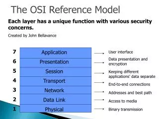
OSI Model……… • The OSI Model is a layered frame work for the designing of n/w systems that allows for communication across all type of computer systems. • It consists of seven layers:-
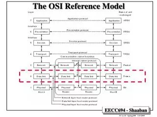
Peer – to – peer Process: • The layer of one device can communicate with the same layer present on the other device through appropriate protocols. This is called peer – to – peer process. EX:- For physical layer the communication is direct. For higher levels the message must move down through the levels of machine ’A’ and at the receiving end, back up through the layers to the appropriate layer.
Each layer in the sending machine adds its own information to the data it receives from the layers just above it and Passes the whole data to the layer just below it. • I.e. each layer adds a header and/or trailer to the data and sends to the layer below it.
Machine ’A’ Machine ’B’ Fig: An exchange using the OSI model
Headers are added to the data at layers 6, 5, 4, 3, 2. Trailer is usually added only at layer 2.
At layer1, the entire packet is converted to a form that can be transferred to the receiving machine. At the receiving machine the message is unwrapped layer by layer with each process receiving and removing the data meant for it.
In the main diagram, in between layers we see interfaces. • The interfaces define what information and services a layer must provide for the layer above it. • Moving of data down through the layers of the receiving machine and back up to through the layers of the receiving machine is made possible only by interfaces.
All the seven layers of the OSI model can be sub-grouped in to three categories: • Network support layers (1,2,3) • User support layers (5,6,7) • Transport layer (4)
N/w support layers deal with the physical aspects of moving data from one device to another. • User support layers allow interoperability among unrelated s/w systems. • Transport layer ensured end-to-end reliable data transmission.
Upper OSI layers are almost implemented in software. • Lower layers are combination of H/W and S/W. • Physical layer is compulsorily a H/W.
Physical Layer: The physical layer is responsiblefor the movement of individual bits from one hop (node) to the next.
Physical layer accepts data from the Data Link layer • And sends the data to the next node/receiving • machine
Responsibilities of Physical layer:- • Physical characteristics of interface and transmission medium • Representation of bits (Optical/electrical) • Data Rate • Synchronization of the bits • Line Configuration • Physical topology • Transmission mode.
2. Data Link Layer • Data link layer receives data from the n/w layer (L3) and passes on to the physical layer(L1) after adding a Header and a trailer.
The data link layer is responsible for moving frames from one hop (node) to the next.
Responsibilities of Data Link Layer:- • Framing • Physical addressing • Flow control • Error control • Access control
3. Network layer • Network layer is responsible for Source-to-Destination delivery of a packet across multiple networks.
The network layer is responsible for the delivery of individual packets from the source host to the destination host.
Note: • If two systems are directly connected, there is usually no need for a n/w layer. • If the two systems ate attached to different n/ws, there is a need for the n/w layer to accomplish Source to destination delivery.
Responsibilities of the n/w layer: • Logical Addressing: (To distinguish the source and destination systems connected on different n/ws. The physical addressing by data link layer handles the addressing problem locally) • Routing
4. Transport layer: • The transport layer is responsible for end-to-end delivery of the entire message • (Note: The n/w layer was responsible for sending a packet rather than the complete message.)
Responsibilities of the Transport layer: • Service – Point addressing • Segmentation and Re-Assembly • Connection control • Flow Control • Error Control
Transport layer…Contd • Service-Point Addressing: Source to Destination delivery means not only from one computer to the another but also from a specific process on one computer to a specific process on the other computer. Therefore the transport layer must include a type of address called service point address or Port address. The n/w layer gets each packet to the correct computer; the transport layer gets the entire message to the correct process on that computer.
Transport layer…Contd 2. Segmentation and Re-Assembly:- A message is usually divided in to transmittable units called as packets. Each segment contains a sequence number. At transport layer these packets are put together in the sequence at which they are transmitted. These numbers enable the transport layer to reassemble the message correctly upon the arrival at the destination & to identify & replace packets that were lost in the transmission.
Transport layer…Contd 3. Connection Control: The transport layer can either be connection-less or connection-oriented. A connectionless transport layer treats each segment as an independent packet and delivers it to the transport layer at the destination machine. A connection oriented transport layer makes a connection with the transport layer at the destination machine first before sending the packets. After all the data are transferred, the connection is terminated.
Transport layer…Contd 4. Flow Control: Here the flow control here is performed end-to-end rather than across the single link. 5. Error Control: Here the error control is done end to end rather than across a single link. Error control at this level is usually achieved through retransmission of the entire packet/message.
5. Session layer: • The Session layer is the network dialogue controller. It establishes maintains and synchronizes the interaction between the communicating systems.
Responsibilities of Session layer: • Dialogue Control • Synchronization
Dialogue control deals with the systems to enter into a dialog. It allows the communication between two processes to take place either in full duplex or Half duplex. • The Synchronization allows to add check points into the stream of data. This will help us in locating the errors when received.
6. Presentation layer • The presentation layer is concerned with the syntax and semantics of the information between two systems.
Responsibilities of Presentation layer: • Translation • Encryption • Compression
Translation: Two different computers may have different encoding systems. The presentation layer at the sender changes the information from its sender dependent format into a common format. The Presentation layer at the receiving machine changes the common format into its receiver dependent format. • Encryption: Used for sending sensitive information. • Compression: Data compression reduces the no. of bits to be transmitted.
7.Application layer Application layer enables the user, whether Human or S/W to access the network. It provides user interfaces and support for services such as emails,remote file access and transfer,Shared DBM & other distributed information services
Responsibilities of Application layer: • Network Virtual terminal • File transfer, access and management (FTAM) • Mail Services • Directory services