Download
1 / 23
260 likes | 572 Views
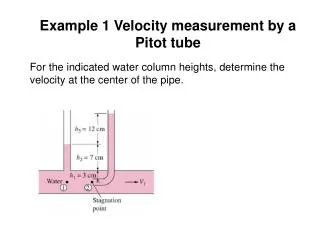
Project 2 Velocity Measurement. Cantilever beam sensors. Position measurement - obtained by strain gauge Acceleration measurement - obtained by the accelerometer What op-amps would you use to get velocity for each?. Basic Steps for Project.

E N D
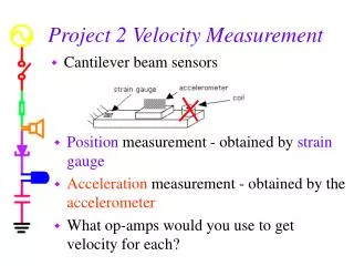
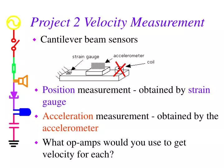
Project 2 Velocity Measurement • Cantilever beam sensors • Position measurement - obtained by strain gauge • Acceleration measurement - obtained by the accelerometer • What op-amps would you use to get velocity for each?
Basic Steps for Project • Mount an accelerometer close to the end of the beam • Wire +2.5V, -2.5V, and signal between IOBoard and Circuit • Record acceleration signal • Reconnect strain gauge circuit • Calibrate the stain gauge • Record position signal • Compare accelerometer and strain gauge signals • Build an integrator circuit to get velocity from the accelerometer sensor • Build a differentiator circuit to get velocity from the strain gauge sensor • Include all calibration and gain constants and compare measurements of velocity
Sensor Signals • The 2 signals • Position • Acceleration
The Analog Device Accelerometer • The AD Accelerometer is an excellent example of a MEMS device in which a large number of very, very small cantilever beams are used to measure acceleration. A simplified view of a beam is shown here.
+2.5V -2.5V Accelerometer • The AD chip produces a signal proportional to acceleration • +2.5V and -2.5V supplies are on the IOBoard. • Only 3 wires need to be connected, +2.5V, -2.5V and the signal vout.
Accelerometer Circuit • The ADXL150 is surface mounted, so we must use a surfboard to connect it to a protoboard
Caution • Please be very careful with the accelerometers. While they can stand quite large g forces, they are electrically fragile. If you apply the wrong voltages to them, they will be ruined. AD is generous with these devices (you can obtain samples too), but we receive a limited number each year. • Note: this model is obsolete, so you can’t get this one. Others are available.
Mount the Accelerometer Near the End of the Beam • Place the small protoboard as close to the end as practical • The axis of the accelerometer needs to be vertical
Accelerometer Signal • The output from the accelerometer circuit is 38mV per g, where g is the acceleration of gravity. • The equation below includes the units in brackets
Position Measurement Using the Strain Gauge • Set up the amplified strain gauge circuit • Place a ruler near the end of the beam • Make several measurements of bridge output voltage and beam position • Find a simple linear relationship between voltage and beam position (k1) in V/m.
Comparing the accelerometer measurements with the strain gauge measurements • The position, x, is calculated from the strain gauge signal. • The acceleration is calculated from the accelerometer signal. • The two signals can be compared, approximately, by measuring ω (2πf).
Velocity • One option – integrate the acceleration signal • Build a Miller integrator circuit - exp. 4 • Need a corner frequency below the beam oscillation frequency • Avoid saturation of the op-amp – gain isn’t too big • Good strong signal – gain isn’t too small
Velocity • Another option – differentiate the strain gauge signal. • Build an op-amp differentiator – exp. 4 • Corner frequency higher than the beam oscillation frequency • Avoid saturation but keep the signal strong. • Strain gauge Differential op amp output is this circuit’s input
Velocity • Be careful to include all gain constants when calculating the velocity. • For the accelerometer • Constant of sensor (.038V/g) [g = 9.8m/s2] • Constant for the op-amp integrator (-1/RC) • For the strain gauge • The strain gauge sensitivity constant, k1 • Constant for the op-amp differentiator (-RC)
MATLAB • Save the data to a file • Open the file with MATLAB • faster • Handles 65,000 points better than Excel • Basic instructions are in the project write up
Some Questions • How would you use some of the accelerometer signals in your car to enhance your driving experience? • If you had a portable accelerometer, what would you do with it?
Typical Acceleration • Compare your results with typical acceleration values you can experience.
Crash Test Data • Head on crash at 56.6 mph Ballpark Calc: 56.6mph = 25.3m/s Stopping in 0.1 s Acceleration is about -253 m/s2 = -25.8 g
Crash Test Data • Head on crash at 112.1 mph Ballpark Calc: 112.1mph = 50.1 m/s Stopping in 0.1 s Acceleration is about -501 m/s2 = -51.1 g
Crash Test Analysis Software • Software can be downloaded from NHTSA website • http://www-nrd.nhtsa.dot.gov/software/
Crash Videos • http://www.arasvo.com/crown_victoria/cv_movies.htm
Airbags • Several types of accelerometers are used & at least 2 must sense excessive acceleration to trigger the airbag.