Download
1 / 39
400 likes | 581 Views
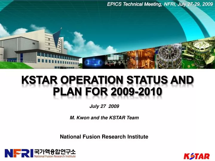
EPICS Technical Meeting , NFRI , July 27-29, 2009. KSTAR Operation Status and Plan for 2009-2010. July 27 2009 M. Kwon and the KSTAR Team National Fusion Research Institute. Outline. Introduction Operation result in 2008 Operation plan for 2009-2010 Longterm Plan

E N D
EPICSTechnical Meeting, NFRI, July 27-29, 2009 KSTAR Operation Status and Plan for 2009-2010 July 272009 M. Kwon and the KSTAR Team National Fusion Research Institute
Outline • Introduction • Operation result in 2008 • Operation plan for 2009-2010 • Longterm Plan • KSTAR Collaboration • Summary
KSTAR mission KSTAR objectives and parameters KSTAR Parameters PARAMETERS KSTAR ITER 1.8 m 0.5 m 2.0 0.8 17.8 m3 56 m2 1.6 m2 DN, SN 2.0 MA 3.5 T 300 s 5.0 H, D-D Nb3Sn, NbTi ~ 28 MW 9 kW @4.5K Major radius, R0 Minor radius, a Elongation, Triangularity, Plasma volume Plasma surface area Plasma cross section Plasma shape Plasma current, IP Toroidal field, B0 Pulse length N Plasma fuel Superconductor Auxiliary heating /CD Cryogenic 6.2 m 2.0 m 1.7 0.33 830 m3 680 m2 22 m2 SN 15 (17) MA 5.3 T 400 s 1.8 (2.5)* H, D-T Nb3Sn, NbTi 73 (110) MW • To develop a steady-state capable advanced superconducting tokamak • To establish the scientific and technological base for an attractive fusion reactor as a future energy source KSTAR & ITER * M. Shimada, et al., Nuclear Fusion, vol. 47, pp. s1 (2007)
Status of the KSTAR tokamak in 2008 Visible spectroscopy KSTAR tokamak Filterscope H mm-wave interferometer ECE Movable hall probe Vacuum pumping system VV : 42,400 l/s, Cryostat : 36,900 l/s ECH 84GHz, 500kW, 2s TV ICRH 30~60MHz, 2 MW, 300s Helium distribution system Supercritical, 4.5K, 600 g/s
Status of the KSTAR tokamak July 10, 2009 New Deck for Movable Prove and XCS
Minimum in-vessel components were installed for the first plasma. In-vessel components 2008 ICRH antenna • Magnetic Diagnostics • Rogowski coils • Vessel curent monitor • Diamagnetic loop • Flux loop • Magnetic probes • Hall probes ECH antenna • Optical Diagnostics • Visible camera • H • Visible spectroscopy • Filterscope • ECE • mm-wave interferometer Inboard limiter Poloidal limiter Glow discharge, Gas injection Movable hall probe
Most of Magnetic Diagnostics , Full scope of Inboard Limiter In-vessel components 2009 Inboard Limiter Boundary Inboard limiter
In-Vessel Component 7 2 4 1 5 6 2 3 Inboard Limiter (2009) 1 Divertor (for double null, 20 sec, 2010) 2 Passive Stabilizer (2010) 3 Poloidal Limiter (2010) 4 In-vessel control coil (2010) 5 NB armor (NBI-1, Port L, 2010) 6 In-vessel Cryopump (2010 ~ 2011) 7
Upgrade Sequence of In-Vessel Component Full Installation of the Inboard Limiter Partial Installation of the Inboard Limiter 2 3 4 Installation of the Divertor System Installation of the IVCC 1 Installation of the Passive Stabilizer Installation of the Poloidal Limiter 5 7 6 8 Installation of the NB Armor Upgrade for 300s 9
Startup scenarios and ECH pre-ionization worked well. Plasma discharge • Startup scenarios • Startup scenarios were prepared considering the limited capacity of power supply. • Compared between conventional & dipole like start up scenarios • ECH pre-ionization • 2nd harmonic ECH pre-ionization was achieved at 1.5 T reduced TF field. • Due to ECH pre-ionization, required loop voltage could be lowered to about 2 V. • 1st harmonic ECH pre-ionization at 3.0 T is planned in 2009. Startup scenario ECH pre-ionization test at dipole-like field configuration ECH pre-ionization test under TF field only • Shot 558 • TF = 13.3kA (1.5 T @ 1.6 m) • ECH = 84 GHz, 500kW, 50ms, Shot 977 TF = 14 kA (1.5 T @ 1.7 m) ECH : perpendicular launch
The target of first plasma was achieved. Plasma discharge • KSTAR succeeded achieving reproducible tokamak plasmas with strict h/w limits of 1.1 Wb in the first trial by combining a unique magnetic configuration and 2nd harmonic ECH preionization, • Circular ohmic plasma discharge (ECH assisted) • Hydrogen plasma • First plasma (107 kA, shot No. 794) was achieved on June 13, 2008. ECH assisted ohmic plasma discharge Basic plasma parameters for first plasmna
ECH pre-ionization study (ITPA HPRT) Pre-ionization study in terms of beam launch direction • ECH pre-ionization test according to beam launch directions • Toroidal scan : normal, co- and counter-oblique injection (+100 ~ -100) • Vertical scan : (z= +10 ~ -10 cm) • The pre-ionization of oblique beam launch was more efficient than the perpendicular launch. Nm-port ECH launch directions Pre-ionization according to beam launch direction CNT-injection Co-injection Ip Bt ECH antenna - mirror pivot R=2800 y=-252 x=-279
ECH pre-ionization study Pre-ionization study in terms of beam power • ECH power threshhold for 2nd harmonic plasma breakdown was about 280 kW. • At least 320 to 350 kW of ECH power was needed for reliable breakdown in KSTAR 1st plasma campaign. • The plasma breakdown time has been reduced with higher ECH power. ECH pre-ionization according to ECH power Pre-ionization delay time • 280 kW(#1078, black) • 320 kW(#1079, red) • 350 kW(#1080, blue) No breakdown (PECH: 280 kW)
EFiTReconstruction • Using all MP’s and FL’s with optimized fitting weight • Vacuum vessel and real limiter structure are considered • Good agreement with CCD camera • Shot 1127 @ t=543.1 msec • Ipl,mea = 97.1 kA, Ipl,rec=98.3 kA, Ivv = 59.3 kA • zout = -9.1 (cm), Rout = 161.2 (cm), a = 35.2 (cm) • zc = -9.3 (cm), Rc = 164.9 (cm) • Good condition no. (7.84 e3) Plasma Current Zout Rout
EFiT Reconstruction Shot 1127 - The effect of Incoloy is not included By O. Hopkins
Understanding Magnetics • Issues for KSTAR magnetics • KSTAR has an inherent source of magnetization inside the PF & TF coils • Incoloy908 is the jacket material for superconducting strand • Weakly ferromagnetic with max μr~10 (saturation B~1T) • Toroidallysymmetric but problematic for field-null quality • Experimental findings : • Downward shift of plasma • Lower measured loop voltage than the calculated by the circuit equations • PF coil currents decay faster than the calculated by the circuit equations • => Need additional up-down asymmetric sources of current and field • Cryostat is a potential source of up-down asymmetry • Large current at the lower cryostat will drive plasma downward • Other discrepancy might be due to cryostat current also Incoloy 908
Understanding Magnetics • A genuine reconstruction code has been developed to cope with nonlinear magnetization from Incoloy 908 in CICC and partially validated with the measurements • still require better understanding of the magnetic probe measurements and its validation • still large discrepancy between the measured and the calculated vessel current • developed analysis tools are directly applicable to ITER TBM analysis • The cryostat is a potential source of up-down asymmetry • according to the calculations, rather large current flows in the cryostat(~200kA) • better agreement with loop voltage measurements with the cryostat circuit • potentially problematic in ITER also • By upgrading and thorough validation of the magnetic diagnostics in next campaign, these issues will be examined in more quantitative way
Two kinds of discharge cleaning methods Wall conditioning (ITPA HPRT) • DC glow discharge cleaning • Glow discharge at zero field conditionat night (H2 & He) • RF discharge cleaning between shots • DC glow is not acceptable due to continuously applied TF field. • KSTAR ICRH system (2 MW, 300 sec, 25 -60 MHz) used for discharge cleaning between shots at 30 kW (30 MHz). • 2 seconds pulse in every 12 seconds for 5-10 minutes just after plasma shot . DC glow discharge using the probe RF discharge using the ICRF system
RF discharge cleaning effects Wall conditioning • ICRF-DC was successfully started without major fault due to the appropriate protection system. • Line density was affected by the shot to shot discharge cleaning. • Exact assessment of residual gas variation due to DC was difficult due to background signals from the pumping lines in RGA system. • Quantitative measurement of wall condition is required with better-set RGA system and increasing pulse length of RF power. RGA signal during DC and plasma shots Line density variation due to ICRH He cleaning ICRH(He)5min Between shots Line density decreases shot by shot 856 857 858
Dust collection and analysis Dust collection and analysis was possible from the virgin operation. • Dust generation was often observed by visible CCD cameras. • Cause : change of heating directions, plasma movement, etc. • Events from in-board limiter and MD protections • Collected dusts at 10 different in-vessel positions using sticky carbon tape. • Large dispersion: 100nm-20um. • Two major peaks at ~100 nm and 2um. • Detected components: C, Si, Mn, P, S, Ni, Cr, Fe, Cl, Ag, Al, Mg • Inboard limiter, Diagnostics (mirror, etc)
Most of the targeted values of the 1st campaign were achieved. Results of the 2008 campaign
Plasma Exp. Operation plan in 2009-2010 Superconducting State Maintain 4.5 K Cryo-facility operation Cool-down from 300 K to 4.5 K and warmup Vacuum pumping system operation Pumping down / Leak check / Wall conditioning
2009 Operation 2010 Operation Available operation time in 2009-2010 • H/W upgrade • Vacuum & wall conditioning • Cool-down & warmup • SC magnet operation • Plasma exp. • H/W upgrade • Vacuum & wall conditioning • Cool-down & warmup • SC magnet operation • Plasma exp. IAEA FEC In Korea
Magnetics Research topics in 2009-2010 • Power supply control • TF magnet test up to 35 kA ; BTF up to 3.5 Tesla @ R=1.8m • PF magnet & power supply control for zero-crossing : Flux up to 2 Weber • Vertical & radial stability control using IVCC (‘10) • Plasma control • Plasma current and position control (Ip, Rp) • Plasma shape control (Rp, Zp,kappa, delta) (‘10) • Magnetic probes & analysis • Refined characterization of the magnetics with additional sensors and electron beam system. (quantifying field errors, calibration of magnetic probes) • Understanding the material (Incoloy908) and geometry effects on plasma
Heating researches Research topics in 2009-2010 • ECH pre-ionization • Full exploitation of 84 GHz & 110 GHz Gryotron • Further Investigation of ECH assisted pre-ionization • Dependence on 1st & 2nd harmonics, injection directions • ICRH heating and RF discharge cleaning • Exploitation of ICRH heating • Exploit RF discharge cleaning between shots • Commissioning of additional heating hevices • NBI (1 MW), LHCD (0.5 MW) (‘10)
Other researches Research topics in 2009-2010 • Wall conditioning & wall interaction • Quantitative approach on wall conditioning & wall recycling • Hydrogen recycling/retention under different wall condition(Boronization, RFGDC, ICRH DC) • Characterization of the dust behavior • Experiments • Disruption studies • Possible MHD Studies ; sawtooth manipulation, lockedmode • Experiments based on the collected proposals (domestic /international) • Data access and collaboration • Data access, analysis, logging • Remote experiments participation & operation
Experimental Proposals • 37 experimental proposals registered through internet • In 7 categories • System commissioning (5) • Magnetic configuration and equilibrium reconstruction (7) • Startup and current ramp-up (4) • Diagnostics (4) • Heating and current drive (3) • Wall conditioning (3) • Instabilities (7) • Transport and confinement (4) • 28 domestic / 9 international • NFRI (18) • Postech (7) • KAERI (3) • GA (5) • PPPL (2) • ORNL (1) • Far-Tech (1)
Remote Experiment (2009, Collaboration with GA) KSTAR site Remote site Connection / transfer Support RSL CMO DSL discussion discussion H323 Remote session leader (RSL) PCS parameter input Web logbook & summary PCS remote GUI parameter Input / limit check Non-PCS parameter confirm Electronic authorization layer Authorization tools N PCS Confirm MDSplus RDB server H323 video. PCS wave server Y “Next Shot is ready” Chief Machine Operator (CMO) Run Shot Wait for live shot updates EPICS / H.323 Shot analysis Shot log Assistant Physics Operator Result transfer MDSplus Local operators Deputy session leader (DSL) Shot summary put to web portal
Key milestones Physics targets Operation target by 2012 • 1st KSTAR operation phase ends • Achieve knowledge on supeconductingtokamak characteristics for H-mode operation • H-mode operation control • Plasma wall interaction research • FEC and RWM control with ELM suppression using IVCC • NTM suppression with ECCD
Long-term plan (mainly by 2017) • Physics target • Targetted for a milestone of ITER construction completion • Plays a role as an ITER pilot • Steady-state operation control • H-mode plasma stabilization for long pulse • AT mode (high beta) operation achievement with available heating systems
KSTAR Collaboration Framework Fusion R&D Collaboration (International) World Leading Experts (International) International Collaboration and Experts Participation JA-WLEs EU-WLEs US-WLEs • ITER Pilot R&D • ITER-IO Domestic Core Research Centers Edge Diag. (Hanyang U.) Heating & CD (KAERI) Divertor & Simulation (KAIST) Reactor Engineering (SNU) Profile Diag. Visualization (POSTECH) EU Support & Collaboration • Simulation R&D • SciDAC (US) • IPERC (JA), etc. US Support & Collaboration • Co-Experiments • ITER Members • Non-ITER JA Support & Collaboration
Summary • KSTAR first-plasma milestone achieved, even with limited hardware capabilities in wall-conditioning, diagnostics, power supply systems etc. • 2008 operation campaign was accomplished in 5 months without any serious fault. • International collaborations were essential to achieve the milestones. • To get meaningful results in 2009 & 2010 campaign, • Acceleration in hardware upgrade, • Careful system operation and concentrated experiment plan, • Accurate measurement and in-detail understanding on SC tokamak operation, and • Stronger domestic and international collaboration are required. • KSTAR control system played a key role to achieve first-plasma milestone.
Thank you for your attention ! At the beginning of the KSTAR cool-down (April. 3, 2008)