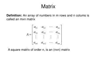
Download
1 / 39
400 likes | 564 Views
MATRIX. Goal To implement a basic structure of a kernel (generic) incorporating Essential features. Real Mode 16 bit x86 I/O File Handling File system Fat 12 Fat 32. MATRIX Features. Booting Memory Program Execution. Security - protect bin files - encryption - priority level.

E N D
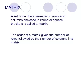
MATRIX MATRIX
GoalTo implement a basic structure of a kernel (generic) incorporating Essential features. MATRIX
Real Mode 16 bit x86 I/O File Handling File system Fat 12 Fat 32 MATRIX Features • Booting • Memory • Program Execution • Security- protect bin files- encryption- priority level MATRIX
Networking -- message transfer- file transfer- ping- listen IO control Key Board Monitor Floppy Hard disk Port Error handling Shell - CLI- Multi page- Multi user Environment support for GUI multithreading MATRIX
Methodology • 1) From Scratch • 2) Oops • 3) Turbo C++ • 4) Nasm MATRIX
Boot Process • Supply On • Bios code at FFF0h is loaded • POST • Video Card detect • Device detect • Startup Screen • System Inventory • Boot sequence BIOS setting • Master Boot Record • Load Boot Loader at 7C00h MATRIX
Registers Segment Registers CS Code, DS Data ,SS Stack, ES Extra Segment. Pointer Registers IP,SP,BP General-Purpose Registers AX Accumulator BX Base CX Count DX Data Index Registers SI DI MATRIX
Memory Map • Interrupt Vector Table 00000 • BIOS Data Area 00400 • PrtScr Status / Unused 00500 • Image Load Address 00600 • Global Data Area 02000 • Application Space 06000 • Boot Loader 07C00 • Available Memory nnnn • 2KB Boot Stack A0000 - 512 - 2KB • Boot Sector A0000 – 512 • Boot Loader A0000 MATRIX
Boot Loader • Loaded at 7c00h • Control passed by bios • Basic Stack Allocation • Load OS at 50h • Control Transfer • Support for both bin, com and exe format MATRIX
Application Loading Aim To load an executable(binary) I Procedure Save CS ,IP and Registers si di for tcc II Call loader parm CS, IP MATRIX
III Search the file Copy to memory (pre defined memory loc) MM IV Pass control to MM V Restore CS IP //int IP = addr(exit funtion cret()) Cret() performs restoring of Registers ,si and di MATRIX
Loader Define the Load segment -600h Save CS & IP -200h Copy file to Load segment Check the file Signature if COM or binary - if Exe -perform relocation -load sp, ss, cs, ip Restore Registers and return MATRIX
Flow Of Control User Authentication Shell - Get user command - Interpret - Process - Error Handling - Multi page Support MATRIX
IO Control • Support for IO primitives • Support for Higher level IO features • CMOS • History MATRIX
Interrupt 10H 16H 15H 19H 1AH Functions Video Support Routines Keyboard Support Routines Delay Support Routines Reboot Functions CMOS Support Routines Bios Routines For IO Control MATRIX
Memory Map • Interrupt Vector Table 00000 • BIOS Data Area 00400 • PrtScr Status / Unused 00500 • Image Load Address 00600 • Global Data Area 02000 • Application Space 06000 • Boot Loader 07C00 • Available Memory nnnn • 2KB Boot Stack A0000 - 512 - 2KB • Boot Sector A0000 – 512 • Boot Loader A0000 MATRIX
FAT 12 Disk Space Clusters Boot Sector + Reserved Regions FAT (store usage of clusters) Root Directory User data area (addressable by cluster) MATRIX
Boot Sector MATRIX
File Allocation Table Structure of the Directory Entries MATRIX
FAT32 File system Structure of hard disk Side (Head) Cylinder (Track/Side) Track Sectors/Track Cluster 1 Sector = 512 Bytes Capacity = Cylinder x Side x Sector x 512 Bytes Sectors = 64 Head = 256 Tracks = 1024 Capacity = 8GB MATRIX
Primary and Extended partitions Primary Partitions MBR Extended Partitions Logical drives Extended Partition Table Partition Table MATRIX
MBR Partition Entry (Part of MBR) MATRIX
Features supported • Similar features which is supported by fat12 • Support for multi-partition • Multi-hard disk support • Developed in OOP Technology MATRIX
Serial Communication • Uses RS232 com ports for communication • Transfer of messages • Ping MATRIX
RS232 Connections MATRIX
Null Modems • A Null Modem is used to connect two DTE's together • It mainly only requires 3 wires (TD, RD & SG) to be wired straight through. The aim is to make to computer think it is talking to a modem rather than another computer. Any data transmitted from the first computer must be received by the second thus TD is connected to RD. The second computer must have the same set-up thus RD is connected to TD. Signal Ground (SG) must also be connected so both grounds are common to each computer. • The connection of other wires depends on whether handshake is needed or not. MATRIX
Connect RX1 to TX2 and vice versa, GND1 to GND2. In addition to this, connect RTS to CTS & DCD and connect DTR to DSR at each end Name Pin Full name Remark ---------------------------------------------------------------------------------------------------------- TxD 3 Transmit Data Data RxD 2 Receive Data Data RTS 7 Request To Send Handshaking CTS 8 Clear To Send Handshaking DTR 4 Data Terminal Ready Status DSR 6 Data Set Ready Status RI 9 Ring Indicator Status DCD 1 Data Carrier Detect Status GND 5 Signal ground Reference level MATRIX
Controls And Status Registers 1st 2nd 3rd 4th Offs. Register -------------------------------------------------------------------------------------------------------------------- 3F8h 2F8h 3E8h 2E8h +0 RBR Receive Buffer Register (read only) or THR Transmitter Holding Register (write only) 3F9h 2F9h 3E9h 2E9h +1 IER Interrupt Enable Register 3F8h 2F8h 3E8h 2E8h +0 DL Divisor Latch (LSB) 3F9h 2F9h 3E9h 2E9h +1 DL Divisor Latch (MSB) These registers can be accessed as word 3FAh 2FAh 3EAh 2EAh +2 IIR Interrupt Identification Register 3FBh 2FBh 3EBh 2EBh +3 LCR Line Control Register 3FCh 2FCh 3ECh 2ECh +4 MCR Modem Control Register 3FDh 2FDh 3EDh 2EDh +5 LSR Line Status Register 3FEh 2FEh 3EEh 2EEh +6 MSR Modem Status Register MATRIX
Initialize - Set baud rate in DL - Set word length and parity in LCR Transmit - Set DTR and RTS bit in MCR to request for permission to send - Check 6th bit in LSR to check whether THRE is empty or not - If empty then send the character to THR Receive - Check status of RTS and DTR to find for any requests - Check for any input data - Stops all incoming data - Get received data from THR MATRIX
Applications • Send messages from one computer to another computer • Check for connection with another computer (ping) using sid MATRIX
Security • Encryption • Priority Levels • Protection MATRIX
, Encryption • Combination of 2 classical encryption techniques are used • Transposition • Substitution • In transposition technique the ordering of characters in the text is changed without changing the character. • In substitution technique the character is changed without changing there relative order in the text • In our encryption algorithm the relative ordering as well as the characters are changed • The process starts by first arranging the text into blocks and then within each block the order of the letters is changed according to the alphabetic order of the key. • Then polyalphabetic substitution is done by adding to each character a specific number given by the pseudorandom series. • By following the above said procedure encryption of user name and passwords are done. • Encrypted user name and password are stored in a fixed place in the hard disk. • No user is given direct access to this place. MATRIX
Priority levels • - We use two priority levels one for the root and another for the user. • - By these priority levels different protection schemes can be introduced. • Protection • A user is not allowed to add or remove any new users This permission is only given to the root. • Protection of system files are done by not allowing any user to view, add, modify or delete these files. MATRIX
Multithreading Class *process -param(no:,function specific values) -status(active,exit) -next -identification -function Eg: function()-Display Random Number Generator MATRIX
Class *process_scheduler -no_process, -deact -cur_proc_no, -halt, -*cur_process; struct { int process_quantom,process_counter; bool act; }process_table[X]; MATRIX
void quantom_checker(PROC *proc) PROC *next_process(PROC *proc) Function-Thread() Set no. of porcesses Create linked-list Call quantom_checker() MATRIX
Mode and Enhancements Real And Protected Modes Features:32 bit,4 GB Benifits -Multitasking,Virtual Memory -security:process and memory MATRIX
Conclusion • The source code is available as OPEN SOURCE - CODE so that OS develepers can modify/upgrade and enhance the project in the future • Future Enhancements that can be done: -Networking -File systems -Optimisation -Device Drivers • Network Booting in devolopment phases MATRIX