Download
1 / 11
110 likes | 269 Views
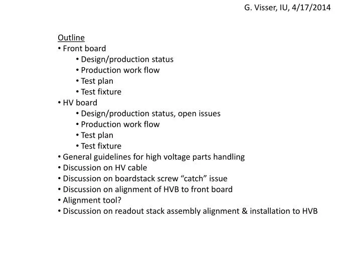
G. Visser , IU, 4/17/2014. Outline Front board Design/production status Production work flow Test plan Test fixture HV board Design/production status, open issues Production work flow Test plan Test fixture General guidelines for high voltage parts handling

E N D
G. Visser, IU, 4/17/2014 • Outline • Front board • Design/production status • Production work flow • Test plan • Test fixture • HV board • Design/production status, open issues • Production work flow • Test plan • Test fixture • General guidelines for high voltage parts handling • Discussion on HV cable • Discussion on boardstack screw “catch” issue • Discussion on alignment of HVB to front board • Alignment tool? • Discussion on readout stack assembly alignment & installation to HVB
Front board status • Have 20 bare boards “front Rev. A” – this is production prototype • Overall mechanical dimensions correct, functionally correct • PMT signals look excellent through pogo pin connection – see next slide • No HV breakdown seen in 24 hours @ 4100 V from HVB • Production problem: 2nd lamination prepreg flows too much into the PMT holes (despite long conversations with the vendor about this, although it is not their fault this is an (unavoidable) issue of the deisgn). • Every board needs rework, with some risk of damage • We will have to do a revision “A-1” hopefully the final production prototype • Instead of 10 mil “no flow” (so-called) prepreg, I am going to try to suggest to the vendor 2 mil “no-flow” prepreg, 6 mil core w/o copper, 2 mil “no-flow” prepreg. • Or, the vendor may have a better alternative suggestion, not sure • 1 front board will used for destructive tests • 1 front board fully assembled and shipped to UH
Front board status Front pogo carrier 5 single-pe events overlayed, amplitude scaled and time shifted 20 GS/s 500 ps/div 5 mV/div ext. att. 0.83 risetime of these pulses ~130 ps Back side of test board
Front board production work flow Receive bare boards from vendor Check each PMT pin hole depth with go gauge pin; check diameter with go/no-go gauge pin set Check width and thickness of the board (height is not a critical dimension) Blow out holes Ultrasonic clean: ethanol, methanol, acetone sequence Press in pin sockets (24 at a time); visual inspect Check thickness of board w/ pin sockets, with gauge plate covering the sockets Solder the capacitors by hand w/ 63/37 tin lead solder, RMA flux Ultrasonic clean: ethanol, methanol, acetone sequence Mount to test fixture and hi-pot test Vacuum bag? Store and ship • Questions: • Do we need to serialize the front boards? • TBD if the cleaning is a limiting step. May need to simplify • Any baking or burn-in needed? • FYI (discuss) I do not plan to check connectivity – is done as bare board test by vendor, assuming later steps will not break anything • Quick check of capacitance w/ DMM is possible. But not clear that it would reliably detect cracked capacitors, so I’m inclined to skip it. • ...?
Front board production & test required items Stereo microscope & illuminator appropriate for typical PCB work PMT hole depth go gauge (IU custom item, to be designed) PMT hole diameter go/no-go gauge pins (McMaster) Shop air (or clean air/filter?) and blowgun, maybe needle-nozzle needed? Hole clearing rework tool (pin vise w/ drill bit and metal sleeve) Calipers for width measurement Micrometer for thickness measurement Pin socket press tooling (IU custom item, to be designed, concepts ~defined) Arbor press (1-ton) and tool blocks Gauge plate ~0.2 inch x approximately same area as board (to be purchased) Metcal solder station w/ appropriate tip, 63/37 tin/lead RMA solder, nonmetallic tip tweezers Cleaning solvents (I still have to discuss w/ CEEM safety officer, may need to relocate this step to a hood, etc.) Ultrasonic cleaner SK-35 fixture ISEG SHQ226L power supply (0 – 6 kV) TBD fixture – either a standard HVB or more likely a modified voltage divider of some kind that allows reliable trip on any flashover in/on HVB Vacuum bag sealer? (one might be available from NOvA @ IU, or we can purchase)
HVboard status • Have 10 bare boards “HVB Rev. B” – this is production prototype • Functionally correct • No HV breakdown seen in 24 hours @ 4100 V • Minor changes planned for rev B-1 • Front edge features to better locate the pogo pin carrier for soldering • Testpoints to apply HV via test fixture pogo pins for test without cables attached • Put board closer to bracket for improved thermal and mechanical arrangement • This might involve moving contact pads on front rev A-1 slightly, ok • 1 HV board assembly completed and shipped to UH
HVB production work flow Receive assembled (sans cables, pogo pins) boards from vendor pre-serialize? (see questions below) Preliminary electrical test @ 1 kV; rework problematic boards Ultrasonic clean: ethanol, methanol, acetone sequence Rivet to HVB bracket Serialize the bracket Check dimension from rear bracket datum to front edge of the board (which is pogo carrier reference position) Solder cables (other end already has connector?? probably) Send to potting vendor Receive potted boards (sans pogo) from vendor Solder pogo carrier Final electrical test @ 3 kV, 4 kV; scrap problematic boards Vacuum bag? Store and ship • Questions: • The finished HVB gets a serial number sticker on bracket. How to track serial number to correlate 1kV preliminary test data? • TBD if the cleaning is a limiting step. May need to simplify • Any baking or burn-in needed? • ...?
HVB production & test required items Stereo microscope & illuminator appropriate for typical PCB work Shop air (or clean air/filter?) and blowgun, maybe needle-nozzle needed? Metcal solder station w/ appropriate tip, 63/37 tin/lead RMA solder Pogo carrier positioning fixture Cleaning solvents (I still have to discuss w/ CEEM safety officer, may need to relocate this step to a hood, etc.) Ultrasonic cleaner HVB test fixture Keithley 2010 DMM w/ ethernet-GPIB bridge attached ISEG SHQ226L power supply (0 – 6 kV) linux PC Arbor press and rivet set tooling Vacuum bag sealer? Go gauge for potting-to-pocket clearance
HV board test plan • Measure DC voltage and possibly also noise (in a representative AC “rms” way) for each tap of each channel. • Do this at 1 kV (before bracket attach) and at 3 kV and 4 kV input (final) • For each, do it with no load, with 10 MΩ for MCPA, with 10 MΩ for MCPB, and with 10 MΩ for both. • That is 160 / 320 measurements per HVB (~5 / 10 min) • The above has to be done once before bracket attach, and again after potting & pogo soldering. • Should we do some burn-in before final test? ( duration=? temperature=?) • Inspect potting with “go gauge” corresponding to cold plate pocket (at MMC). • Inspect pogo pins for free travel and correct distance from free end to rear-of-bracket datum. • To do this test plan we need: • Test board with means to contact HVB (incl. without pogo pins), with switching of DMM to different test points and with HV divider, and with switched 10 MΩ loads • Control/DAQ software for the switches and DMM readout, and limit checking, and some kind of database/storage • Go gauge for potting • Pogo position inspection gauge
HV board test setup Test ½ HVB at a time (move to two different positions on test fixture) HVB D.U.T. (1/8 shown) Keithley 2010 K HE12-1A83-03 OPA140 MCPAT 10 MΩ MCPAB TBD MCPBT 10 MΩ MCPBB GND ISEG SHQ226L (0 – 6 kV) PC / linux 4 HVB channels on each PS channel
Discussion on readout stack assembly alignment & installation to HVB alignment step a little bigger? hex driver access hole diameter a little bigger? we should just capture the screws, not unnecessarily constrain the angle of a driver coming in there. (ball-end is assumed) how to evenly push the stack forward to compress pogo pins and seat the alignment step on HVB bracket? Is this really feasible, to work in presence of the cables and in the confined space for outer boardstacks, and tell the difference between seating or not seating on the alignment step? add some other way to verify stack to HVB bracket alignment? what is the consequence of an open pogo connection? [I have accidentally done it, seems nothing was damaged, but I am not sure this is guaranteed.] there should be a torque spec on the HVB mounting screws, boardstack internal screws, and the boardstack to HVB mounting screws, or we may have thermal troubles develop after installation.