Download
1 / 9
90 likes | 247 Views
Beam Pattern for a Single Slot Antenna. Larry Isenhower Summer 2002. At first I was writing LabView programs to talk with many different instruments in the lab to get their information onto a computer.

E N D
Beam Pattern for a Single Slot Antenna Larry Isenhower Summer 2002
At first I was writing LabView programs to talk with many different instruments in the lab to get their information onto a computer. Then I began to make measurements on a scale model single slot planar antenna to make a far field beam pattern to help test simulations that have been made for the actual antenna. What exactly am I doing?
The antenna I am mapping is a scale model for a possible antenna that may be used to study the Cosmic Microwave Background (CMB) This new antenna will be sensitive to the polarization of the CMB and will be smaller than existing antennas. What will the antenna be used for?
What is the CMB? • It is the oldest light in the universe. • The CMB allows astronomers to find many fundamental parameters. • This is the CMB power spectrum obtained from current data. From Max Tegmark’s webpage
The antenna • First I needed to verify that our antenna resonated at the correct frequency that we had predicted.
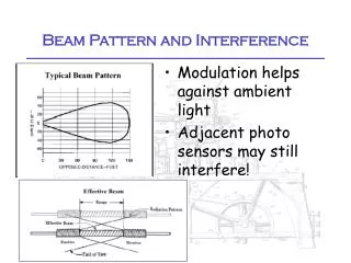
Far Field beam map • After having verified that the antenna really did resonate at the predicted frequency I moved on to make a Far Field beam map.
Still more about the antenna • We also had a lens made for the antenna. The main peak occurs at 30 degrees because of the slot being off center, but we don’t know what is causing the asymmetry.
Where I stand now • I have finished mapping the single slot antenna. • The next step is to figure out the problem with our lens. • Then we would get a scale model of the actual antenna that we will be using in our experiments and test that.