Download
1 / 64
640 likes | 648 Views
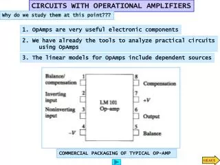
Chapter 14: Operational Amplifiers. Basic Op-Amp. The electronic amplifier: is an electronic device that increases the power of a signal.

E N D
Basic Op-Amp The electronic amplifier: is an electronic device that increases the power of a signal. Operational amplifier or op-amp, is a very high gain differential amplifier (that amplifies the difference between two voltages)with a high input impedance (typically a few meg-Ohms) and low output impedance (less than 100 W). Note the op-amp has two inputs and one output. 2
Op-Amp Gain • Op-Amps have a very high gain. They can be connected open-loop or closed-loop. • Open-loop refers to a configuration where there is no feedback from output back to the input. In the open-loop configuration the gain can exceed 10,000. • Closed-loop configuration reduces the gain. In order to control the gain of an op-amp it must have feedback. This feedback is a negative feedback. A negative feedback reduces the gain and improves many characteristics of the op-amp. 4
CMRR One rating that is unique to op-amps is CMRR or common-mode rejection ratio. Because the op-amp has two inputs that are opposite in phase (inverting input and the non-inverting input) any signal that is common to both inputs will be cancelled. Op-amp CMRR is a measure of the ability to cancel out common-mode signals. 12
Inverting Op-Amp • The signal input is applied to the inverting (–) input • The non-inverting input (+) is grounded • The resistor Rf is the feedback resistor. It is connected from the output to the negative (inverting) input. This is negative feedback. 20
Inverting Op-Amp Gain Gain can be determined from external resistors: Rf and R1 Unity gain—voltage gain is 1 The negative sign denotes a 180 phase shift between input and output. Constant Gain—Rf is a multiple of R1 21
Virtual Ground An understanding of the concept of virtual ground provides a better understanding of how an op-amp operates. The non-inverting input pin is at ground. The inverting input pin is also at 0 V for an AC signal. The op-amp has such high input impedance that even with a high gain there is no current from inverting input pin, therefore there is no voltage from inverting pin to ground—all of the current is through Rf. 22
Practical Op-Amp Circuits Inverting amplifier Noninverting amplifier Unity follower Summing amplifier Integrator Differentiator 23
Inverting/Noninverting Op-Amps Inverting Amplifier Noninverting Amplifier 24
Summing Amplifier Because the op-amp has a high input impedance, the multiple inputs are treated as separate inputs. 26
Integrator The output is the integral of the input. Integration is the operation of summing the area under a waveform or curve over a period of time. This circuit is useful in low-pass filter circuits and sensor conditioning circuits. 27
Differentiator The differentiator takes the derivative of the input. This circuit is useful in high-pass filter circuits. 28
Op-Amp Specifications—DC Offset Parameters Even when the input voltage is zero, there can be an output offset. The following can cause this offset: • Input offset voltage • Input offset current • Input offset voltage and input offset current • Input bias current 29
Input Offset Voltage (VIO) The specification sheet for an op-amp indicate an input offset voltage (VIO). The effect of this input offset voltage on the output can be calculated with 30
Output Offset Voltage Due to Input Offset Current (IIO) If there is a difference between the dc bias currents for the same applied input, then this also causes an output offset voltage: • The input offset Current (IIO) is specified in the specifications for the op-amp. • The effect on the output can be calculated using: 31
Total Offset Due to VIO and IIO Op-amps may have an output offset voltage due to both factors VIO and IIO. The total output offset voltage will be the sum of the effects of both: 32
Input Bias Current (IIB) A parameter that is related to input offset current (IIO) is called input bias current(IIB) The separate input bias currents are: The total input bias current is the average: 35
Frequency Parameters • An op-amp is a wide-bandwidth amplifier. The following affect the bandwidth of the op-amp: • Gain • Slew rate 36
An op-amp is designed to be a high-gain, and wide-bandwidth amplifier. This operation tends to be unstable (oscillate) due to positive feedback . To ensure stable operation, op-amps are built with internal compensation circuitry, which also causes the very high open-loop gain to reduce with increasing frequency. This gain reduction is referred to as roll-off. A number of circuit improvements result from this gain reduction. 1.More stable amplifier voltage gain 2.Incresing the input impedance of the circuit over that of the op-amp alone. 3. Decreasing the circuit output impedance from that of the op-amp alone. 4. Increasing the frequency response of the circuit over that of the op-amp alone.
Bandwidth a measure of the width of a range of frequencies As the frequency of the input signal increases the open-loop gain drops off until it finally reaches the value of 1 (unity). A frequency at which the gain becomes 1, since the frequency band from 0 Hz to the unity-gain frequency is also a bandwidth. Op-amp specifications provide a description of the gain versus bandwidth.
Slew Rate (SR) Slew rate (SR) is the maximum rate at which an op-amp can change output without distortion. The SR rating is given in the specification sheets as V/s rating. 39
Maximum Signal Frequency The slew rate determines the highest frequency of the op-amp without distortion. where VP is the peak voltage 40
General Op-Amp Specifications • Other ratings for op-amp found on specification sheets are: • Absolute Ratings • Electrical Characteristics • Performance 41
Absolute Ratings These are common maximum ratings for the op-amp. 42
Electrical Characteristics Note: These ratings are for specific circuit conditions, and they often include minimum, maximum and typical values. 43
What is the range of the voltage-gain adjustment in the circuit: