Download
1 / 34
360 likes | 583 Views
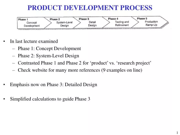
PRODUCT DEVELOPMENT PROCESS. In last lecture examined Phase 1: Concept Development Phase 2: System-Level Design Contrasted Phase 1 and Phase 2 for ‘product’ vs. ‘research project’ Check website for many more references (9 examples on line) Emphasis now on Phase 3: Detailed Design

E N D
PRODUCT DEVELOPMENT PROCESS • In last lecture examined • Phase 1: Concept Development • Phase 2: System-Level Design • Contrasted Phase 1 and Phase 2 for ‘product’ vs. ‘research project’ • Check website for many more references (9 examples on line) • Emphasis now on Phase 3: Detailed Design • Simplified calculations to guide Phase 3
WING IN GROUND EFFECT PROJECT Boeing has recently taken interest in the WIG phenomenon and proposed a concept for a massive craft to meet a US Army need for a long-range heavy transport. Called the Pelican, the 500 ft (153 m) span vehicle would carry up to 2,800,000 lb (1,270,060 kg) of cargo while cruising as low as 20 ft (6 m) over water or up to 20,000 ft (6,100 m) over land. Unlike the Soviet concepts, the Pelican would not operate from water, but from conventional runways using a series of 76 wheels as landing gear.
EXAMPLES: EKRANOPLAN CRITERIA FOR SUCCESS • Example 1: • Optimize weight vs. takeoff distance ratio: > 111 kg/m (Boeing 747, ref [8]) • Comments: • Clear target number with literature substantiation • Never actually done in report • How can such a calculation be performed? • Example 2: • Have a Lift vs. Drag: > 150 • Comments: • At what condition? • Why do you need 150? • Range, endurance calculations to show the benefit of L/D=150
EXAMPLES: EKRANOPLAN CRITERIA FOR SUCCESS • Example 3: • Achieve a transportation efficiency: >> 0.23 kg/hour/kW (modern turbo-diesel barge, ref [6]) • Comments: • A clear goal, a clear number that is a target • Corroborate with literature • How do measure that? • Example 4: • Achieve good cost effective design • Comments: • What does ‘good’ mean? • How do you determine if it is ‘cost effective’? • ‘Cost effective’ by whose standards?
EXAMPLES: EKRANOPLAN • Objective/Goal Statements: • “Data gathered from our wind tunnel testing will hopefully allow the team to develop a system of permanent equations that will allow us to mathematically show why ground effect vehicles are more efficient and which designers can use to design WIG vehicles in the future.” • “Use CFD to model ground effect” • Comments: • Great idea, correlate data from wind tunnel and experiment to develop new predictive methods • Already been shown why and how ground effect augments lift • Wind tunnel testing is effective, but can some simply models be developed to understand the phenomena and make predictions? • How does the wing tunnel testing and CFD fit together?
EKRANOPLAN: POTENTIAL ANALYSIS • Consider the potential flow generated by a pair of cylinders located in a cross-stream, V∞, each with radius R, and located at x = 0, y = ±A (A>R). • Write the y and f for this flow, and derive the velocity components. Show that there exists a plane of symmetry at y = 0 where vertical velocity is zero. • Show that there exists a streamline that runs along this axis of symmetry. Note: This streamline can be used to represent a ‘ground plane’, and thus this potential flow combination – a source doublet and its ‘image doublet’ represents a cylinder in ground effect. • Derive expressions for the coefficients of lift and drag for the cylinder located about the ground. How do they vary as the cylinder gets closer to the ground (i.e., the cylinder and its image get closer together)? • What are implications of this results for an airplane trying to land on a runway? A V∞ R
SPACECRAFT SLOSH Boeing’s Delta IV Heavy • Upper-stages of expendable vehicle fleet undergo orbital maneuvers that may lead to large propellant slosh motions • Slosh motion can affect vehicle performance • Example: reorientation maneuver may cause liquid propellant to exit through pressure relief valves designated for gas venting leading to uncontrollable dynamic instability • Example: cryogenic liquid may splash onto hot sections of tank side walls and dome leading to large boil-off of propellant • Example: NEAR spacecraft interrupted its insertion burn when fuel reaction was larger than anticipated. Prevented NEAR from orbiting Eros and delayed mission • Example: Does Orion need baffles? • Models needed to predict impacts of propellant slosh for various mission scenarios • Limited database to benchmark CFD codes in very low-gravity (low-acceleration) environments Lockheed Martin’s Atlas V 401
SIMPLE SLOSH • Actual situation looks highly complex: droplets, wave break-up, non-uniform surface thickness, does not look exactly the same with time (transient behavior) • However, simple models capture the general behavior of lateral slosh • Two simple models (1) Pendulum Model, and (2) Spring-Mass Model
MODEL VS. DATA COMPARISON • Comparison of simple model with experimental data: ± 10 – 20 %
EXAMPLE OF CFD CALCULATION • CFD provides additional details • Important to ask whether or not you need these details for the level of fidelity required • Before you do a CFD calculation, ask yourself: • Why am I doing this? • Is there a cheaper, faster way to get what I want?
OTHER SPRING-MASS-DAMPER SYSTEMS • Provides: damping ratio, natural frequency, sensitivity to various parameters • Numerous models in existence: car suspension, microphone, control systems, electromechanical systems, etc.
MESSAGES FROM SLOSH EXAMPLE • When natural event looks very complicated, try to look at basic physics of what is happening • Try to determine if small details are important or not • Which small details can be neglected (for the time being) • Spring-Mass-Damper models are extremely powerful • Simple to develop and solve • Economical in terms of time and money • How do you know if it is right or wrong? • What are the weak parts? • How do you test it? • When do you trust it?
PROPELLER EXAMPLE • Many student projects have looked at variable angle propellers for UAVs • Various levels of complexity to model such a flow → various levels of accuracy result • What level of accuracy do you need?
SIMPLE PROPELLER: ACTUATOR DISK THEORY • Neglect rotation imparted to the flow. • Assume the Mach number is low so that the flow behaves as an incompressible fluid. • Assume the flow outside the propeller streamtube has constant stagnation pressure (no work is imparted to it). • Assume that the flow is steady. Smear out the moving blades so they are one thin steady disk that has approximately the same effect on the flow as the moving blades (the ``actuator disk''). • Across the actuator disk, assume that the pressure changes discontinuously, but the velocity varies in a continuous manner.
MESSAGES FROM PROPELLER EXAMPLE • When using CFD, be able to say in your report: • We needed a CFD model/solution to get ___________ • The results of the CFD solution were used to __________ • A simpler model was insufficient because it did not capture ________ • When using a simplified model, be able to say in your report: • The assumptions in the simplified model are 1) __________, 2) _________ • Assumption (1) is valid because __________ • Assumption (2) is valid because __________ • The model was developed to predict _________ • The results of the model were used to _________ • This model does not capture the details of __________
COMBUSTION KINETICS EXAMPLE • Many prior senior design projects involved combustion • Consider Methane Combustion • This looks awfully simple – when written as a 1-step process • Equation says nothing about how long the process takes to happen • Approach taken by team from 2005-2006 in project goals: • “Model kinetics of combustion process…” CH4 + 2O2 + 7.52N2 → CO2 + 2H2O + 7.52N2 + heat Air Products Fuel
GLOBAL AND QUASI-GLOBAL MECHANISMS • ‘One-step mechanism’ • Parameters: A, Ea/R, m and n • Chosen to provide best fit agreement between • Experimental and predicted flame temperatures, as well as flammability limits • Can be implemented in Excel
MESSAGES FROM KINETICS EXAMPLE • Don’t just perform literature review on your global problem – nothing might exist • Literature review on specific pieces • When specific pieces are put together, then you have something new • Knowing what is good enough • Do you need all 279 steps? • Be able to articulate why you do, or why you don’t • What are the strengths and weaknesses of a global 1-step mechanism?
COMBUSTOR EXAMPLE Commercial PW4000 Combustor Military F119-100 Afterburner
MAJOR COMBUSTOR COMPONENTS Turbine Compressor
MAJOR COMBUSTOR COMPONENTS • Key Questions: • Why is combustor configured this way? • What sets overall length, volume and geometry of device? Fuel Combustion Products Turbine Air Compressor
APPLICATION TO COMBUSTION SYSTEM MODELING Turbine Air Primary Zone f~0.3 f ~ 1.0 T~2500 K Compressor Conceptual model of a gas-turbine combustor using 2 WSRs and 1 PFR
GAS TURBINE ENGINE COMBUSTOR MODEL • Consider the primary combustion zone of a gas turbine as a well-stirred reactor with volume of 900 cm3. Kerosene (C12H24) and stoichiometric air at 298 K flow into the reactor, which is operating at 10 atm and 2,000 K • The following assumptions may be employed to simplify the problem • Neglect dissociation and assume that the system is operating adiabatically • LHV of fuel is 42,500 KJ/kg • Use one-step global kinetics, which is of the following form • Ea, is 30,000 cal/mol = 125,600 J/mol • Concentrations in units of mol/cm3 • Find fractional amount of fuel burned, h • Find fuel flow rate • Find residence time inside reactor, tres
MESSAGES FROM COMBUSTOR EXAMPLE • Complex physical systems can often be reduced to 1D systems • If you didn’t do the literature review, you would have no idea that such models already exist • Make use of models that already exist – there is no need to reinvent such models when they are already in place (and tested, and benchmarked) • Inventing a new models vs. using one that is already in existence
OVERALL MESSAGES • Why am I developing a model? • What do I need to get out of it? • How will that result be used for the project? • Can I assume the problem is steady-state? • Can I remove time? • Is the situation that I am looking at replaceable by a static one? • Can I model the problem as 1-D? • What is the dominant direction in which things are happening? • Find similar situations in text books • Don’t expect to find the exact model of what you are doing • Add levels of complexity sequentially – don’t go for the homerun ball right away • Must understand each physical process on their own before looking at interaction • Shows progress
HOW DOES IT REALLY WORK? CFD Simplified Models Experiments
HOW DOES IT REALLY WORK? CFD Simplified Models Experiments
HOW DOES IT REALLY WORK? CFD • Everyone trusts the experiment except the person that ran it • No one trusts the CFD except the person that ran it Simplified Models Experiments