Download
1 / 40
400 likes | 543 Views
Team Gnomes Presents. P38X9-WXZZZ45397ERV.JAS95_MGD A “Black Box” solution to turning old monitors into digital picture frames. Outline of Presentation. Team member introduction Overview of Project Block Diagram Major Component Selection Packaging Design Specifications

E N D
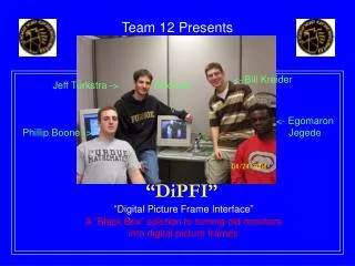
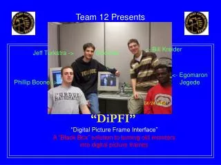
Team Gnomes Presents P38X9-WXZZZ45397ERV.JAS95_MGD A “Black Box” solution to turning old monitors into digital picture frames
Outline of Presentation • Team member introduction • Overview of Project • Block Diagram • Major Component Selection • Packaging Design Specifications • Circuit Design and Schematic
Introduction • Egomaron Jegede – Rabbit/Packaging specialist • CmpE, graduating 5/2004 • Bill Kreider – IR specialist • EE, graduating 5/2004 • Phil Boone – Rabbit specialist • CmpE, graduating 5/2004 • Jeff Turkstra – Epson specialist and maniacal team leader • CmpE, graduating 5/2004
Outline of Presentation • Team member introduction • Overview of Project • Block Diagram • Major Component Selection • Packaging Design Specifications • Circuit Design and Schematic
Overview of Presentation • Image data provided via ethernet from a PC is displayed on a VGA compatible device. • Data made available via a client program that decodes the JPEG and takes care of communicating with our device • Scales image appropriately • Adjusts color depth • Ensures proper image format • VGA display is done via Epson controller interfacing with a 4MB memory chip. • IR remote control allows product to be placed in a difficult to reach location • Allows one to change the picture with just a push of a button! • Accomplished with Reynolds Electronics Sony IR decoder and a Sharp IR receiver.
Outline of Presentation • Team member introduction • Overview of Project • Block Diagram • Major Component Selection • Packaging Design Specifications • Circuit Design and Schematic
Digital Picture Box Block Diagram Power Supply 9V DRAM Network Server Ethernet EPSON Graphics Controller Rabbit Microprocessor IR Receiver/Decoder Data Bus VGA Output Reset Controller PLD’s (Data and Address Multiplexing)
Outline of Presentation • Team member introduction • Overview of Project • Block Diagram • Major Component Selection • Packaging Design Specifications • Circuit Design and Schematic
ComponentSelection Rationale Specific Design Constraints Required for the Graphics Chip and Micro Controller Comparison of Selected Chips to Alternatives
Required Functionality of the Graphics Controller • Ability to create and refresh all the analog RGB signals necessary to display an image independently • Standard DRAM interface for the frame buffer • Large enough frame buffer size to hold a standard SVGA image
Contestant #1: Epson Embedded RAMDAC LCD/CRT Controller • Onboard analog RGB output • Support for external standard EDO/FPM DRAM chip up to 2 megabytes • Surface mount with 128 pins • Detailed 500 page technical manual
Contestant #2: Cirrus Logic System-on-a-chip with CRT/LCD Controller • Onboard analog RGB output • Support for external standard EDO/FPM DRAM • Surface mount with 240 pins • ISA bus, onboard ARM controller, sound output, and PS/2 serial interface
Cirrus Logic 240 pins Additional features: ISA bus, ARM controller, etc. Poor documentation External frame-buffer Epson 128 pins 500+ page technical manual including timing diagrams, interfacing examples, etc. External frame-buffer Which graphics controller better suits the needs of our project?
Winner? Epson S1D13505 • Additional features of the other chip are not applicable to our project • Detailed Documentation • Fewer pins
Required functionality of the Microcontroller • Large number of I/O pins to communicate with the Epson’s huge bus(21-bit address, 16-bit data) and an IR chip • Enough computability to buffer large amounts of data • Integrated network adapter • Efficient development environment
Contestants? No contest. • Due to the network requirement, a Rabbit controller is ideal • Need a large model to accommodate the I/O pin demand • High speed required to buffer large amounts of data • Modest amount of flash memory and RAM to buffer data
Winner? Rabbit 3010 Core Module(based on Rabbit 3000) • Total of 52 I/O pins(46 pins required for the Epson alone) • 256kb of Flash Memory • 128kb Static RAM • 29.4 Mhz clock
Outline of Presentation • Team member introduction • Overview of Project • Block Diagram • Major Component Selection • Packaging Design Specifications • Circuit Design and Schematic
Packaging Design • Design Requirements • Commercial Product Comparison • Unique/adapted features • Weight and Cost Estimate
Packaging Design • Physical Features - RJ-45 network connector - 15 pin female VGA connector - Power and Busy LED’s - Push buttons ( Next, Previous, Function, Power ) - Internal electronics : Epson , Rabbit ,IR Receiver/Decoder, PLD’s - Power input - Casing
Commercial Product Analysis - #1 • Features - Wall mountable - Loads pictures via CD-ROM or internet via Ethernet -Displays JPEG/MPEG-1 and MP3’s - Remote control Digi-Frame DF-1710 WxHxD : 17.83” x 14.5” x 2.9”
Digi-Frame Pros and Cons • Hidden functionality behind slim frame • Variable mounting (vertical or horizontal) • Large, clear display size (13”x10”) • Not portable due to weight (19lbs.) • CD-R0M drive affects mounting
Unique Aspects of the Digital Picture Box Design • Separates image processing from display allowing great flexibility on choice of display screen and size ( Any VGA controlled display screen) • Small size makes design highly portable and unobtrusive
Commercial Product Analysis - #2 • Features - Plays JPEG/MPEG/MP3 file formats - Supports various memory cards and has USB driver - compatible with Windows and Mac OS - Interfaces with NTSC/ Pal TV’s or TFT monitors - IrDA remote control Vosonic Multi-media Viewer – 80 WxHxD : 98 x 89 x 15 mm Weight : 81g
Product features we plan to copy/adapt to our design • Compact light-weight design • User-friendly button arrangement and labeling • Arrangement of inputs and outputs allow for easy connection • Wide front panel for easy IR signal reception
Initial Packaging Concept Digital Picture Box (Top/Front view) Digital Picture Box – Rear view
Outline of Presentation • Team member introduction • Overview of Project • Block Diagram • Major Component Selection • Packaging Design Specifications • Circuit Design and Schematic
Circuit Design and Schematic: Considerations • Power supply considerations • Rabbit 3000 operates at 3.3 VDC • Can sink and source up to 6.8 mA current • Input pins are up to 5.5 VDC tolerant • IR module operates at 5 VDC • Requires 4 I/O pins @ < 2 mA operating current per pin
Circuit Design and Schematic: Considerations • Power supply considerations • Epson Graphics Controller requires two separate power supplies • Analog 3.3 VDC • Digital 3.3 VDC • These must be separated so that digital switching noise does not inject itself, through a common ground, into the analog portion of the circuit. This would be very undesirable and a decrease in VGA display quality would be observed.
Circuit Design and Schematic: Considerations • Power supply considerations • Epson Graphics Controller requires two separate power supplies • Analog 3.3 VDC • Digital 3.3 VDC • To prevent switching noise from entering the analog circuitry: • Two separate power supplies will be used. • A ferrite bead will be used to connect the analog to the digital ground at a single, regulated point. The bead will block high-frequency noise. • Several 0.1 uF decoupling capacitors will also be used.
Circuit Design and Schematic: Considerations • Power supply considerations • To achieve required voltages, a standard unregulated 9 VDC “Wall Wart” will be used along with standard Low-Dropout Voltage Regulators to achieve: • 9 V to regulated VL 3.3V digital power • 9 V to regulated Analog VL 3.3V analog power • 9 V to regulated VL 5V digital power
Circuit Design and Schematic: Considerations • IR Remote • Sharp receiver outputs the signal that drives transmitter on a remote control • Reynolds Electronics Sony IR Remote Decoder takes output from receiver and toggles a data pin corresponding to button presses on the remote. Can recognize buttons 0-9, channel +/-, and volume +/- on any Sony remote. • Operates at 5 VDC, but will be compatible with Rabbit I/O pins’ 5.5 VDC voltage limit and 6.8 mA current limit
Circuit Design and Schematic: Considerations • VGA Connector • Standard VGA connector fed by Epson RGB signals • Ferrite beads for low-pass filtering • BAV99 double-diode for surge protection • LED/Pushbuttons • Only consideration is meeting 6.8 mA Rabbit source/sink limits
Circuit Design and Schematic: Considerations • Epson Graphics Controller considerations • 21 bit address bus • 16 bit data bus • Direct connection to 256k x 16 EDO RAM chip • Standard VGA connections • RGB outputs – RED/GREEN/BLUE • Horizontal/Vertical Controls – HRTC/VRTC • Important Control Signals • Chip Select – CS# • Write Enable – WE1#/WE0# • Reset – RESET# • IREF • Requires 4.6 mA current reference supplied by NPN transistor
Circuit Design and Schematic: Considerations • Other Design Considerations • 25.175 MHz Crystal Oscillator • 256k x 16 EDO DRAM • PLDs • Reset Controller
Future work • Prototype major components • Complete board layout • Set up network server • Software Development
References for Major Components [1] Rabbit 3000 Core Module http://shay.ecn.purdue.edu/~477grp12/datasheets/rabbit3000_core_manual.pdf [2]Epson Graphics Controller http://shay.ecn.purdue.edu/~477grp12/datasheets/epson_manual.pdf [3]Low-Dropout Voltage Regulators 3.3V http://focus.ti.com/lit/ds/symlink/reg103-33.pdf 5V http://focus.ti.com/lit/ds/symlink/reg103-5.pdf [4]PLD 26V12 http://www.vantis.com/lit/docs/datasheets/pal_gal/26v12.pdf 16V8 http://www.vantis.com/lit/docs/datasheets/pal_gal/16v8.pdf
References for Major Components IR [5] Detectorhttp://shay.ecn.purdue.edu/~477grp12/datasheets/sharp_ir_detector_data.pdf [6] Decoderhttp://shay.ecn.purdue.edu/~477grp12/datasheets/rentron_ir_decoder.pdf [7] DRAM http://www.issi.com/pdf/41xx16256.pdf [8] Crystal Oscillator http://www.eea.epson.com/go/Prod_Admin/Categories/EEA/QD/Crystal_Oscillators/all_oscillators/go/Resources/TestC2/SG8002DB