Download
1 / 22
220 likes | 379 Views
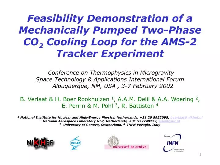
Feasibility Demonstration of a Mechanically Pumped Two-Phase CO 2 Cooling Loop for the AMS-2 Tracker Experiment Conference on Thermophysics in Microgravity Space Technology & Applications International Forum Albuquerque, NM, USA , 3-7 February 2002

E N D
Feasibility Demonstration of a Mechanically Pumped Two-Phase CO2 Cooling Loop for the AMS-2 Tracker Experiment Conference on Thermophysics in Microgravity Space Technology & Applications International Forum Albuquerque, NM, USA , 3-7 February 2002 B. Verlaat & H. Boer Rookhuizen 1, A.A.M. Delil & A.A. Woering 2, E. Perrin & M. Pohl 3, R. Battiston 4 1 National Institute for Nuclear and High-Energy Physics, Netherlands, +31 20 5922095, bverlaat@nikhef.nl 2 National Aerospace Laboratory NLR, Netherlands, +31 527248229, adelil@nlr.nl 3 University of Geneva, Switzerland, 4 INFN Perugia, Italy
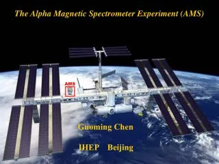
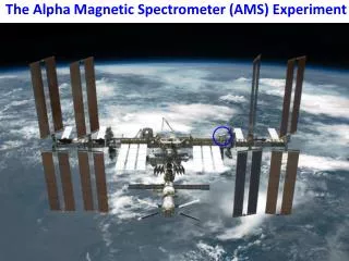
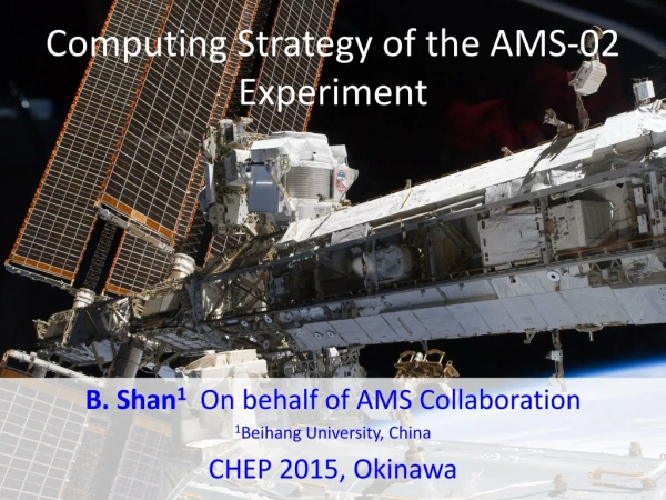
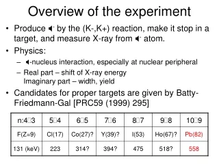
AMS-Experiment overview • AMS is a space born particle detector originating from the international high energy physics community. AMS is financed by NASA/DOE and the collaborating institutes. • AMS is seeking for cosmic anti-matter, dark matter and missing matter originating from distance galaxies. • The AMS-mission consists of a completed precursor flight (STS-91, may 1998) and a planned 5 years mission as attached payload on the International Space Station, scheduled to be launched on Space Shuttle flight UF-4 (march 2004)
AMS Missions AMS’ final mission as attached payload on the ISS (STS Mission UF4, March 2004) AMS-1 Payload AMS-1 situated in the back of Discovery’s cargo bay on STS-91 (May 1998) as a precursor flight.
Alpha Magnetic Spectrometer Detector overview Cosmic Particles Particle track detection in the Tracker Space Shuttle Cargo Bay
Radiators for the Tracker (2x1.3m2) 192 Watt The AMS-2 Silicon Tracker detection surface 112 individual Electronic assemblies producing each 1-3 Watt of heat Tracker Thermal Control System(TTCS)
TTCS main design constrains: • The AMS-1 Tracker will be re-used for the AMS-2 mission. The TTCS need to fit the existing hardware. • 112 individual heat sources spread over the outer periphery of the Tracker • All 112 heat sources must be controlled on the same temperature level (<1°C) between 0°C and 10°C, with limited orbital variations (<3°C). • Low TTCS mass allowed in the Tracker. (Field of view disturbance) • Low thermal gradient to the radiators, due to the limited radiator area.
TTCS investigated concepts and trade-off: • Capillary Pumped Systems (LHP or CPL). • Too many spread heat sources (=>112 evaporators!). • Severe amount of mass in the Tracker • Serious integration problems • A two-stage concept, using a collecting heatpipe and CPL/LHP for transport to the radiators. • Better choice than the single CPL system. • Heatpipe (Ø10mmx1500mm) is large and difficult to integrate. • Serial mechanically Pumped loop (Single/two-phase). • The only serious option for a multiple heat input system like the Tracker Heat colleting heat pipe with CPL connection to the radiators
Detection surface Electronics (Heat Sources) cooling tube 2 loops of 10 m length MPL concept in the Tracker
TTCS-MPL baseline concept:A redundant series loop with Carbon dioxide as working fluid. Why Carbon dioxide? • Hardly no safety related problems, not toxic! • Very low Liquid/Vapour density ratio O(1-10), crucial for a series 2-phase system. (Ammonia O(100-1000)) • High evaporative heat transfer coefficients (2-20 kW/m2K) • Good refrigerant around 0ºC evaporation temperature. • In the case of the AMS-Tracker: • Small tube dimensions (3 mm OD) in case of 2 parallel loops • Low mass in the Tracker field of view. • Possibility of following the stepped orientation of the heat sources. • Direct thermal contact (Efficient heat transfer). • No foreseen integration problems. • No CTE problems • Very low temperature gradients (<1ºC) over the evaporator length (ca. 10m). • Possibility of implementing a fully redundant system.
CO2 phase diagram TTCS operating area
DAQ Tube 1 CO2 Bottle 99.995% Tube 2 Expansion valve Tube 3 Tube 4 To gas heater, spring relieve valve and flow meter Pressure gauges CO2 Feasibility Test Set-Up. Test Set-Up schematic Feasibility demonstration of the TTCS serial evaporator using CO2 Pressure drop and temperature gradient measurements using a venting test.
Feasibility Test Results. Flow direction Evaporator length (9.3m) Nominal condition Specified maximum gradient
TTCS CO2 circulation system overview: (Preliminary) • Mechanical circulation pump in the liquid line. • Loop pressure/evaporation temperature control using a two-phase accumulator. • Heat exchangers between the in and outlet of the evaporator for efficient preheating of the sub-cooled liquid. • Orbital load damping using out of phase WAKE and RAM radiators. • Heatpipe radiators to minimize debris puncture risk of the TTCS pressurized volume.
TTCS CO2 loop design overview The complete TTCS integrated in AMS Detailed view of the TTCS evaporator connection to the Tracker hybrids Artists impression of the TTCS CO2 evaporator in AMS
On going TTCS research activities: • Evaporator research: • Pressure drop measurements • Heat transfer coefficients • Thermal control: • Heat exchanger feasibility Schematic of the prototype CO2 loop at NIKHEF.
Photos of the TTCS Test Loop at NIKHEF. Heat exchanger Thermal control reservoir AMS-like evaporator Pump Level indicator Transparent section for flow pattern study Condenser in thermostat bath
Power dependent pressure/temperature drops for a 10 m long, 2.5 mm ID evaporator at 0°C
0 0.1 0.2 0.3 0.4 0.5 0.6 Vapour quality (-) Vapour quality and power dependence of the heat transfer coefficient and observed flow patterns, for a 2.5 mm ID tube at a flow rate of 2.7 g/s and a temperature of 5°C
Heat exchanger performance at nominal conditions (100 Watt, 2.7 g/s, 5ºC) Flow direction
TTCS response on a varying condenser temperature with a heat exchanger.
Conclusions • The TTCS evaporator concept with CO2 as working fluid fulfills the thermal specifications of AMS-Tracker • The discussed TTCS evaporator concept is fully compatible with the rest of the AMS experiment hardware. • The presence of a heat exchanger between the in and outlet of the evaporator show a positive impact on the dynamic behavior of the TTCS • Based on this feasibility demonstration the AMS-collaboration decided to accept the discussed TTCS proposal as base-line cooling system for the AMS-Tracker (Nov. 2001)