Download
1 / 8
80 likes | 193 Views
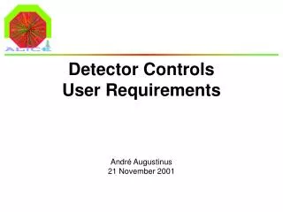
Detector Controls Layout. Introduction. Motivation. Capture the current state of knowledge on your controls layout Also triggered by “installation review” Concentrate on the hardware layout of your control system Get an idea on what, where, how many

E N D
Detector Controls Layout Introduction DCS Workshop
Motivation • Capture the current state of knowledge on your controls layout • Also triggered by “installation review” • Concentrate on the hardware layout of your control system • Get an idea on what, where, how many • Radiation and accessibility for equipment in the cavern • See Robert’s talk this afternoon DCS Workshop
Method • Provided you with a drawing showing our knowledge (TDR, URD, presentations, discussions) • Appended a list of questions • Requested you to show today an update of the drawing and answers to the questions • Example for muon tracker DCS Workshop
Muon-Trk 28 ? ? 1 1 20 328 ? 1 156 ? ? 444? ? ? ? 07/03/03 [FSM?] Database(s) PVSS II PVSS II PVSS II Control room (ACR) OPCclient DIMclient User interface Ethernet PVSS II PVSS II PVSS II PVSS II OPC client OPC client OPC client OPC client CAEN OPC ? Wiener OPCserver Wiener OPCserver ? OPCserver DIMserver (?) OPC/DIM Server (?) SchneiderOPCserver PCI-CAN PCI-CAN PCI-CAN ? E C C C E E CAEN PLC ? PLC(?) C P Wiener VME(wiener?) I/O device(PLC,Wago,ELMB?) ELMB HV Gas Air/Water cooling LV Switch Geometrymonitor HV DDL Detector Detector Crocus Detector Detector Detector High Voltage Low Voltage Crate Control Environment monitor Geometry Detector Cooling Gas system
“Generic” architecture for the DCS “back end” User interface; main console for detector operation Main PVSS tasks; interface to field layer, Finite State Machine, … Database tasks (reading and writing). This depicts a task on one or more PC’s, there is no one-to-one correspondence between boxes and PC’s [FSM?] Database(s) PVSS II PVSS II PVSS II OPCclient DIMclient User interface Ethernet PVSS II PVSS II OPC client OPC client CAEN OPCserver Wiener OPCserver DIMserver SchneiderOPCserver Field and process layer, with their processes DCS Workshop
Muon-Trk 28 ? ? 1 1 20 328 ? 1 156 ? ? 444? ? ? ? 07/03/03 [FSM?] Database(s) PVSS II PVSS II PVSS II Control room (ACR) OPCclient DIMclient User interface Ethernet PVSS II PVSS II PVSS II PVSS II OPC client OPC client OPC client OPC client CAEN OPC ? Wiener OPCserver Wiener OPCserver ? OPCserver DIMserver (?) OPC/DIM Server (?) SchneiderOPCserver PCI-CAN PCI-CAN PCI-CAN ? E C C C E E CAEN PLC ? PLC(?) C P Wiener VME(wiener?) I/O device(PLC,Wago,ELMB?) ELMB HV Gas Air/Water cooling LV Switch Geometrymonitor HV DDL Detector Detector Crocus Detector Detector Detector High Voltage Low Voltage Crate Control Environment monitor Geometry Detector Cooling Gas system
Explanation of the detector drawings, field and process layer 1 3 3 This depicts a task on a PC, each box does not necessarily correspond to a single PC PVSS II The software interface at the client side (e.g. OPC client in PVSSII) OPC client XYZ OPCserver The software interface to the equipment (e.g. commercial OPC server) PCI-XYZ C The interface to the equipment (e.g. CAN or Profibus interface). [ethernet interfaces are not indicated] This depicts the communication media or type of cable (see table) This indicates the number of busses or cables Cable and/or Bus Areas at ALICE Ethernet E This depicts equipment to be controlled. CAN bus C Alice Control Room (ACR) Counting Rooms in PX25 (CR1 – CR4) and Plug Cavern, outside L3 magnet Cavern, inside L3 magnet Profibus P This indicates the number of units (usually crates) ISEG Serial (RS232) S Signal cable HV cables HV HV This depicts the cable from the equipment to the hardware (see table) LV cables (+busbar) LV Other/Unknown This indicates the number of cables or channels Liquid or Gas Detector DCS Workshop This depicts the hardware connected
Final remarks • The information presented today should be reflected in your URD’s • Please send me a copy of your slides DCS Workshop