Download
1 / 1
10 likes | 112 Views
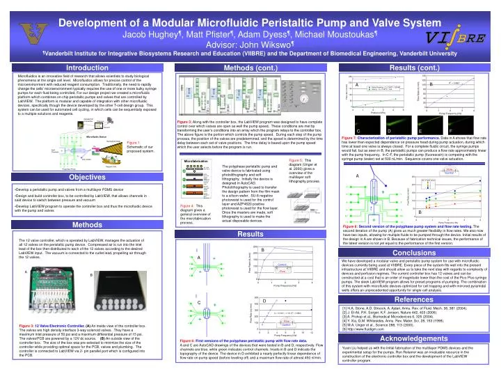
Microfabrication. UV Light and mask. 1. photo-resist on silicon wafer. 2. hardened structure positive-relief. 3. positive-relief with PDMS epoxy. 4. cured PDMS on glass coverslip.

E N D
Microfabrication UV Light and mask 1 photo-resist on silicon wafer 2 hardenedstructure positive-relief 3 positive-relief with PDMS epoxy 4 cured PDMS on glass coverslip Development of a Modular Microfluidic Peristaltic Pump and Valve SystemJacob Hughey¶, Matt Pfister¶, Adam Dyess¶, Michael Moustoukas¶Advisor: John Wikswo¶¶Vanderbilt Institute for Integrative Biosystems Research and Education (VIIBRE) and the Department of Biomedical Engineering, Vanderbilt University Introduction Results (cont.) Methods (cont.) Microfluidics is an innovative field of research that allows scientists to study biological phenomena at the single cell level. Microfluidics allows for precise control of the microenvironment with reduced reagent consumption. Traditionally, the need to rapidly change the cells’ microenvironment typically requires the use of one or more bulky syringe pumps for each fluid being controlled. For our design project we created a microfluidic platform which combines on-chip peristaltic pumps and valves that are controlled by LabVIEW. The platform is modular and capable of integration with other microfluidic devices, specifically though the device developed by the other T-cell design group. This system can be used for automated cell cycling, in which cells can be sequentially exposed to a multiple solutions and reagents. B A Figure 3: Along with the controller box, the LabVIEW program was designed to have complete control over which valves are open as well the pump speed. These conditions are met by transforming the user’s conditions into an array which the program relays to the controller box. The above figure is the portion which controls the pump speed. During each step of the pump process, the position of the valves are predetermined, and the speed is determined by the time delay between each set of valve positions. The time delay is based upon the pump speed which the user selects before the program is run. A C D F E Figure 7:Characterization of peristaltic pump performance. Data in A shows that flow rate has lower than expected dependence on pressure head during pump actuation, during which time at least one valve is always closed. For a complete fluidic circuit, the syringe pumps would fail, but as seen in B, the peristaltic pumps can produce a flow rate approximately linear with the pump frequency. In C-F, the peristaltic pump (fluorescein) is competing with the syringe pump (water) set at 500 nL/min. Sequence covers one valve actuation. Figure 1: Schematic of our proposed system. Figure 5: This diagram (Unger et al. 2000) gives a overview of the multilayer soft lithography process. The polyphase peristaltic pump and valve device is fabricated using photolithography and soft lithography. Initially the device is designed in AutoCAD. Photolithography is used to transfer the design pattern from the film mask to a silicon wafer. SU-8 negative photoresist is used for the control layer and AZP4620 positive photoresist is used for the flow layer. Once the masters are made, soft lithography is used to make the actual disposable devices. Flow Control A Objectives • Develop a peristaltic pump and valves from a multilayer PDMS device • Design and build controller box, to be controlled by LabVIEW, that allows channels in said device to switch between pressure and vacuum • Develop LabVIEW program to operate the controller box and thus the microfluidic device with the pump and valves Figure 4: This diagram gives a general overview of the microfabrication process. B Methods Figure 8:Second version of the polyphase pump system and flow rate testing. The second iteration of the pump (A) gives us much greater flexibility in flow rates. We also now have two inputs, allowing for multiple fluids to be pumped through the device. Initial results of the design in A are shown in B. Because of fabrication technical issues, the performance of the latest version is not yet equal to the performance of the first version. Results The 12 valve controller, which is operated by LabVIEW, manages the actuation of all 12 valves on the peristaltic pump device. Compressed air is run into the inlet lead of the box then distributed to each of the 12 valves according to the desired LabVIEW input. The vacuum is connected to the outlet lead, propelling air through the 12 valves. B Conclusions A We have developed a modular valve and peristaltic pump system for use with microfluidic devices currently being used at VIIBRE. Every piece of the system fits well into the present infrastructure at VIIBRE and should allow us to take the next step with regards to complexity of devices and perfusion regimes. The current controller box has 12 valves and can be constructed at a cost that is an order of magnitude lower than the cost of the Pico Plus syringe pumps. The sleek LabVIEW program allows for preset programs of pumping. The combination of this system with microfluidic devices optimized for cell trapping and with mirrored pyramidal wells offers an unprecedented opportunity for single cell analysis. Control A Flow B References D C [1] H.A. Stone, A.D. Stroock, A. Ajdari, Annu. Rev. of Fluid. Mech. 36, 381 (2004). [2] J. El-Ali, P.K. Sorger, K.F. Jensen, Nature 442, 403 (2006). [3] A. Prokop et al., Biomedical Microdevices 6, 325 (2004). [4] Y. Xia, G.M. Whitesides, Annu. Rev. Mater. Sci. 28, 153 (1998). [5] M.A. Unger et al., Science 288, 113 (2000). [6] http://www.fluidigm.com Flow Control Figure 3:12 Valve Electronic Controller. (A) An inside view of the controller box. The valves are high density interface 3-way solenoid valves. They have a maximum inlet pressure of 50 psi and a maximum differential pressure of 15 psi. The valves/PCB are powered by a 12V dc source. (B) An outside view of the controller box. The size of the box was pre-selected to minimize the size of the controller while providing optimal space for the PCB, valves and plumbing. The controller is connected to LabVIEW via 2- pin parallel port which is configured into the PCB. Acknowledgements Figure 6:First versions of the polyphase peristaltic pump with flow rate data. A and C are AutoCAD drawings of the devices that were tested in B and D, respectively. Flow channels are blue, while green indicates control channels. Insets in B and D indicate the topography of the device. The device in D exhibited a nearly perfectly linear dependence of flow rate on pump speed (before leveling off) and a maximum flow rate of almost 450 nl/min. Yuxin Liu helped us with the initial fabrication of the multilayer PDMS devices and the experimental setup for the pumps. Ron Reiserer was an invaluable resource in the construction of the electronic controller box and the development of the LabVIEW controller program.