Download
1 / 9
90 likes | 117 Views
Explore the implementation of MIPS architecture focusing on memory-reference, arithmetic-logical, and control flow instructions. Dive into functional units, clocking methodologies, latches, flip-flops, and edge-triggered techniques.

E N D
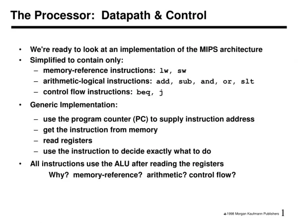
The Processor: Datapath & Control • We're ready to look at an implementation of the MIPS architecture • Simplified to contain only: • memory-reference instructions: lw, sw • arithmetic-logical instructions: add, sub, and, or, slt • control flow instructions: beq, j • Generic Implementation: • use the program counter (PC) to supply instruction address • get the instruction from memory • read registers • use the instruction to decide exactly what to do • All instructions use the ALU after reading the registers Why? memory-reference? arithmetic? control flow?
More Implementation Details • Abstract / Simplified View:Two types of functional units: • elements that operate on data values (combinational) • elements that contain state (sequential)
falling edge cycle time rising edge State Elements • Unclocked vs. Clocked • Clocks used in synchronous logic • when should an element that contains state be updated? • choose falling or rising edge as active
An unclocked state element • The set-reset latch • output depends on present inputs and also on past inputs
Latches and Flip-flops • Output is equal to the stored value inside the element (don't need to ask for permission to look at the value) • Change of state (value) is based on the clock • Latches: whenever the inputs change, and the clock is asserted • Flip-flop: state changes only on a clock edge (edge-triggered methodology) A clocking methodology defines when signals can be read and written — wouldn't want to read a signal at the same time it was being written
D-latch • Two inputs: • the data value to be stored (D) • the clock signal (C) indicating when to read & store D • Two outputs: • the value of the internal state (Q) and its complement • Here, signal changes on rising clock edge
D flip-flop • Output changes only on the clock edge (here on falling clock edge)
Our Implementation • An edge triggered methodology • Typical execution: • read contents of some state elements, • send values through some combinational logic • write results to one or more state elements
Simple Implementation • Include the functional units we need for each instruction Why do we need this stuff?


