Download
1 / 32
320 likes | 344 Views
Mathematical models of hemodynamic as an instrument for solution of related medical problems. S.Mukhin, N.Sosnin, V.Koshelev, A.Bunicheva, M.Abakymov, A.Khrulenko, A.Dreval, A.Borzov, V.Lukshin Lomonosov Moscow State University, CMC department. http://vm.cs.msu.su/.

E N D
Mathematical models of hemodynamic as an instrument for solution of related medical problems S.Mukhin, N.Sosnin, V.Koshelev, A.Bunicheva, M.Abakymov, A.Khrulenko, A.Dreval, A.Borzov, V.Lukshin Lomonosov Moscow State University, CMC department. http://vm.cs.msu.su/ Moscow, 2014, 29-31 October, Fourth International Workshop on the Multiscale Modelling and Methods in biology and medicine.
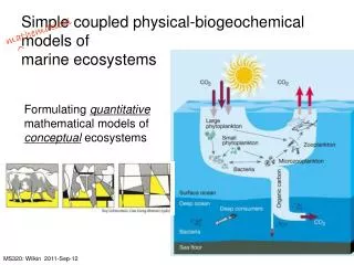
Local models 2D-3D simulation in complex domain with respect to elastic properties, rheology of blood, etc., on the base ofNavier-Stokes equations. + + Aneurysm Stenosis Heart ,
Global model CVSS The aim is to carry out estimation of hydrodynamic blood flow (velocity, pressure, cross-section) along the graph, which is physiologically adequate to human cardiovascular system, and to represent the main characteristics of of blood circulation system CVSS - Cardio-Vascular Simulating System- project and software
Global model Edgesof the graphcorrespond to different vessels or to a set of small vessels. Nodesof the graphrepresentareas of vessels bifurcation ortissuesand organs. Each organ must be described by specific model, in the simplest case - point model. Models, associated to the node of graph, can be so complex as the stated problem requires. Model of Heart Models of interaction Model of stomach Model of intestine Model of liver Model of kidney
Global model S(x2) S(x1) X X2 X1 Hemodynamic equations S(t,x) –cross-section area u(t, x) -velocity of blood flow p(t,x) -pessure Q(t,x) - blood flow (Q=Su) t – time, x - local space coordinate - blood density ( = const). Diameter of vessel can be constant or not constant and may depends upon a great number of physiological and physical parameters, such as pressure, coefficient of flexibility, gravitation, etc. This dependence we will call the “equation of state” S=S(P,…). Walls of vessel is supposed to be thin. If dS/dp>0
Global model Q t Q t General principals of blood flow mathematical description • 1. The use of conservation laws • 2. Quasi one-dimensional approach • 3. The account of viscous effects • 4. The account of external forces influence (acceleration, gravitation, vibration, etc.) • 5. In practice, velocity u(t,x) of blood flow is much less then the speed (t,x)of propagation of small disturbances, u / <<1. • 6. Non-stationary flow. Heart output flow Q or pressure p are given as time dependent functions (for example, periodical functions). • Non-stationary flow in looped (closed-up) system of vessels with given or self-regulating heart output flow or pressure functions
Global model p mm Hg ptop pbot tsystdias t, сек auricle Heart as an elements of integrated model QA QV Heart is described bytwoorfourchambers heart model. ventricle “Two chambers” heart model consists from two cells: auricle and ventricle, and is considered as a pump. During the systole blood from ventricle propagates into aorta according to the given Q or P function, which depends not only upon time, but upon stroke volume, current auricle and ventricle volume, aortic arch baroceptors and so on. During the diastole auricle is filling up. “Four chambers’ model is arranged from “two chambers” models with different characteristics. Systemic circulation Lungs A simplest example of “two chambers” heart model , ,
Global model v i,j –numbers of converging arches in this node, zi– considering the direction of local edge coordinates. Kd- Darcy coefficient Mathematical model on a graph 1. To each edge (vessel) of a graph corresponds a “hemodynamic” system of equations 2.To each node of a graph, which is “a bifurcation node”, two bifurcation equations are corresponded 3 . To each node, which represent tissue, mass conservation law and specific model are corresponded. NOTATIONS S(t,x) –cross-section area u(t, x) -velocity of blood flow p(t,x) -pressure t - time x - local space coordinate - blood density ( = const). FT – viscous force FT – external force
CVSS Project Numerical methods and algorithms 1. Special format of graph description was constructed. It allows user to pay no attention to the way how solver treats the topology of vascular graph. 2. Conservative implicit finite-difference scheme with second order of approximation on each arch of graph was taken as a base. At the same time scheme is homogeneous, so it does not depends upon concrete arch. 3. Two different variants of finite- difference schemes provided for better reliability of numerical calculations. 4. The total non-linear system of equations is solved with help of iteration methods (Newton method, successive iterations on coefficients of equations).
Mass transfer (CVSS) Thought the hemodynamic parameters are known, possibility to calculate transfer of substances by blood appears. Let us assume, that - mass concentration of l -th substance in k- th vessel, then mass transfer along the vessels net is described by system of equations with boundary conditions at each inner node (linking conditions) where describe the external mass flows and chemical reactions correspondingly. and
W1 Mass transfer (CVSS) Mass transfer in vessel – conservative approximation - mass flow Conservation law W2 X1 X2 X1 X2
Mass transfer (CVSS) Conservation law – area of bifurcation W1 W2 X1 X2 l1 l2 m (Node) l0 X0 W0
Linear analysis Linear approximation of hemodynamic equations (LHMD) Evolution of small disturbances of velocity and pressure from stationary solutions of hemodynamics is described on each arch of vascular graph by the system of linearized hemodynamic equations: This system of equations supplied with linearized equation in internal nodes of graph: and with linearized boundary conditions in boundary nodes of graph.
Coefficients and we name “transport coefficients”. They control the evolution of velocity and pressure waves when they pass through bifurcation nodes of vascular graph and determine amplitudes of formed waves. Each of progressing waves is described by the following formula: Coefficient determines amplitude of velocity wave while passing from arch j to arch i j i i Coefficient determines amplitude of velocity wave in arch i while reflecting from node
CVSS Project Features of 3D CVSS (Cardio-Vascular Simulating System) software. • The representation of an arbitrary three-dimensional graph of • cardiovascular system with the possibility of building it up, as well as narrowing. • Spatial graph frame model topology and parameters editor. • Automatically generated 3D model from the spatial graph frame model. • Possibility to move the graph in general, as well as its parts in space in order to take into account the influence of gravity when changing body position. • The use of realistic 3D models for visualization of blood vessels and • the calculation results in the familiar visual form. • The development of advanced tools for editing, storage and control • significantly increased input data volume. • Multi-threaded implementation of a sofware for parallel computation • process and visualization of the results.
Applications • Modelingoffunctioningofthecirculatorysystemandits regulation. • Simulationandinvestigationof CVSdiseasesand theirtreatments. • Modeling theinfluenceofvariousorgansonthefunctioningofCVS. • Modelingtheinfluenceof CVStopologychanges (asaresultofsurgery, injuries, etc.) • Modelingofcirculatorysysteminfluenceofthefunctioningofvariousorgans. • Simulationoftransferby thecirculatorysystemofvarioussubstances (gases, enzymes, drugsandsoon) andtheirinfluensondifferentorgans. • Etc.
A hemodynamic factor of arterial vesselaneurism development Typical location of artery aneurism thoracic aorta Willis circle With the help of developed technique it is possible to construct a matrix of passing and reflection coefficients in the nodes of vascular graph. An evident correlation between typical locations of artery aneurism of cerebral arteries (Willis circle), of thoracic aorta and certain numerical values of corresponding determinants of the matrix was noted.
g Gravitational influence Theoretical studies of viscous fluid (blood) flow in the net of elastic vessels allow to understand, what are the problems which must be solved in order to carry out modeling of gravitational influence. The performed methodic allows to investigate the influence of gravitational forces on human hemodynamics. Numerical simulation on a full graph (systemic circulation + cerebral circulation) helps to investigate changes in hemodynamics under growing gravity Volume of blood in brains strongly falls under influence of gravitation force Blood supply of brain sections also decreases
Gravitational influence middle cerebral artery femoral artery
Model graph of brain arteries View of brain arteries Cerebral hemodynamics modeling The first step in hemodynamics modeling is the construction of certain vascular graph. Let us consider the graph of main brain arteries up to the third order of bifurcation. Collaterals Brain tissues Circle of Willis According to the task of cerebral hemodynamics modeling the complexity of vascular graph can be different. Presented graph includes heart, arch of aorta, scheme of arms,vertebral arteries, carotids, Willis circle, arteries P1,P2,P3, A1,A2,A3,M1,M2,M3, collaterals and some others. Venous return presented schematically. The influence of the rest CVS described by “point model”. Heart “Point” model of the rest part of CVS Arms
Multiscale Modeling. Solution of 2D or 3D Navier-Stokes equations in selected vessels in order to investigate the flow in area of vessels wall singularities. Such approach allows to analyze the mutual influence of global and local hemodynamics. This is actual when blood flow studded in cases of stenosis,thrombus, etc. While global hemodynamics is computed in quazi one-dimensional case and is tuned on possibilities of PC, local 3D flow calculations may need parallel HPC abilities. Global hemodynamics gives relevant boundary conditions for local 2D-3D modeling
Modeling insulin and glucose dynamics. • For the simulation of the spatial-time dependant dynamics of glucose and insulin we need: • To be able to estimate (model) blood flow in the closed CVS ( ! ), • To carry outcomputation of the processin network vessels for a long time (up to 16-20 hours). • To be able to count (simulate) the transfer of at least of two substances in this system. The algorithm should be conservative ( ! ). • To formalize (to described in mathematical terms) the processes of glucose incom and excretion; to formalizeproduction of insulin and excretion of insulin, depending on the level of sugar. • To determine the parameters of the model( ! ).
Modeling insulin and glucose dynamics. On the base of endocrinological tests and clamp tests it is possible to tune personal parameters of the model On the base of CVSS quasi one- dimensional methodic • Main organs and tissues are taken into account (the set may be expanded) • Glucose and insulin sources can be placed anywhere in the system in order to simulate normal and bolus insulin and glucose income. • Productionand interference of both substances can be configured to represent normal or pathologicalglucose-insulin dynamics. • Graph of vessels can be designed to suit ordered physiological accuracy, thus allowing to research in details glucose and insulin redistribution, specific to the considered diabetes mellitus. Modeling of insulin and glucose distribution is based on the high accuracy algorithm of their transfer with blood flow, income and elimination.
Modeling insulin and glucose dynamics. The effect of “delay” in the propagation of glucose. Map of glucose and insulin rate shows the distribution of those substances in every point of vessel at any time Glucose in femoral artery and vein Glucoseburden Average level of glucose increase Average level of glucose decrease It appears, that concentration of glucose stays on the high level for significant time in femoral veins (and in some other veins) even when the level of glucose in check-points (arms and abdominal wall) is satisfactory.
Artificial pancreas The artificial pancreas is a developing technology which is aimed to provide people with diabetes automatically control of blood glucose level and to provide insulin replacement. Current project refers to the medical equipment approach: - using of insulin pump under closed loop control - using real-time data from a continuous blood glucose sensor Analysis and calculation of dose Control Insulin injection Pump Patient Sensor • Main elements : • precise insulin pump • continues real-time sensor of glucose level • real-time calculation of bolus (the amount of insulin which must be delivered to patient) The main attention is paid to the program , which is the key factor.It is necessary to develop a precise algorithm whichcalculates the right amount of insulin at the right time.
Artificial pancreas To develop an intelligent and predictive algorithm for computing real-time insulin injection control it is necessary : To process a huge amount of accumulated physiological data To study qualitativeandquantitativecharacteristics of spatial distribution of insulin and glucose in vessels net To personalize data (endocrinological tests) To determine profilesof requiredbolusaccording tovariouspeculiaritiesofthepatientunder different glucose burden To specify characteristictimes and ratesofcirculatinginsulininsystemofbloodvesselsin dependence upon the point of its injection ETC. Development of computer simulation and mathematical models of insulin production, intakeof glucose and regulationofglicemiacan significantly ease the construction of control utility.
Exchange. The exchange of substances in tissues u(x,r,t) – mass concentration in interstitial fluid, C(x,r,t) - mass concentration in blood F– sorption flow, F1- flow from/to the vessel. F1=Fd +Fp, Fd – diffusion flow, Fp – “pressure” flow In general Fd= λ(C-u)κ, Fp=σ(u,c)ΔP P Ft blood flow Fv x Fp Fp Fd Fv - Pressure in vessel Ft - Pressure in tissue ΔP=Fv-Ft
Lymphatic system Lymphatic system,a subsystem of the cardiovascular system, consists of a network of vessels, tissues, and organs (the same as CV). • The topology of lymphatic system is similar to the topology of CV system. • Lymph flow is described with the same hemodynamic equations. • The same, as in the case of CV, algorithms used to describe net and to solve the problem numerically. • More over, both nets (CV+L systems) we consider as uniform system from algorithmic point of view. Fundamentally important : Modeling of mass transfer along lymphatic net. Connection with CV system via tissues.
Lymphatic system New features (in comparison with CV) • Lymph – contains a lot of components • Lymphatic vessels – specific equation of state, low internal gradient of pressure, valves • New organs – new complex physiological and biochemical models of : • Lymph nodes • Spleen • Thymus New hydrodynamic problem: what is the cause of lymph movement? We consider two effects: Pressure drop along the system Both models need fine tuning Muscle pump (due to valves)
Neurolymph motion Kelly’s model What causes the motion of spinal fluid ? It is supposed, that the pulsating cerebral blood flow in area, restricted by solid cranial bones, causes pulsating lymph flow. Volume of cerebral blood upon time arterial venous Experiment: appr. 1.0 ml per cardiac cycle Total volume Numerical modeling: appr. 1.48 ml per cardiac cycle
Mathematical model of haemodynamics of cardio-vascular system / М. Abakumov , К. Gavriluk, N.Esikova et al. // Differential Equations ( in Rus.)— 1997. — Vol. 33, № 7. — p. 892–898. • Analysis and comparison of some analytic and numerical solutions of hemodynamic problems / I. Ashmetkov, A. Khrulenko, S. Mukhin et al. // Differential Equations. — 2000. — Vol. 36, no. 7. — P. 1021–1026. • An averaged nonlinear model of hemodynamics on the vessel graph / A. Bunicheva, S. Mukhin, N. Sosnin, A. Favorskii // Differential Equations. — 2001. — Vol. 37, no. 7. — P. 949–956. • Mathematical modeling of some applied problems in haemodynamics / A. Bunicheva, S. Mukhin, N. Sosnin et al. // Computational Mathematics and Modeling. — 2002. — Vol. 13, no. 4. — P. 382–412. • Numerical experiment in hemodynamics / A. Bunicheva, S. Mukhin, N. Sosnin, A. Favorskii // Differential Equations. — 2004. — Vol. 40, no. 7. — P. 984–999. • Mukhin S., Sosnin N., Favorskii A. The effect of viscous friction on pulse waves // Differential Equations. — 2006. — Vol. 42, no. 7. — P. 1041–1056. • Analytic study of stationary hemodynamic flows in an elastic vessel with friction / S. Mukhin, M. Menyailova, N. Sosnin, A. Favorskii // Differential Equations. — 2007. — Vol. 43, no. 7. — P. 1011–1015. • Borzov A., Mukhin S., Sosnin N. Conservative schemes of matter transport in a system of vessels closed by the heart // Differential Equations. — 2012. — Vol. 48, no. 7. — P. 919–928. • Studying the influence of gravitational overloads on the parameters of blood flow in vessels of greater circulation / A. Bunicheva, M. Menyailova, S. Mukhin et al. // Mathematical Models and Computer Simulation. — 2013. — Vol. 5, no. 1. — P. 81–91. • Thank you for attention Sergey Mukhin, prof., Department of Computational Methods, Faculty of Computational Mathematics and Cybernetics, Moscow State Univesity, Leninskie Gory,Moscow, Russia. e-mail:vmmus@cs.msu.su, web:http//vm.cs.msu.ru