Download
1 / 75
750 likes | 861 Views
ILC - Operations International Accelerator School on Linear Colliders Sokendai, Shonan Village, Hayama 総合研究大学院大学 湘南村 葉山. Integrated luminosity is the goal – peak luminosity is only a demonstration. Marc Ross, SLAC. Integrated luminosity:.

E N D
ILC - OperationsInternational Accelerator School on Linear Colliders Sokendai, Shonan Village, Hayama総合研究大学院大学湘南村 葉山 Integrated luminosity is the goal – peak luminosity is only a demonstration Marc Ross, SLAC
Integrated luminosity: • Integrated luminosity = Peak luminosity x time x derating factors • Peak luminosity requires charge (power) and low emittance • At specified energy • Integrated performance requires • reliability • stability • controls • diagnostics • system understanding • Operations, as a field in itself: • ‘operations engineering’ or ‘industrial engineering’ • describes how to assess and optimize the utilization of a facility
Integrated luminosity • Time accounting • Impact of lost time can be substantial • How long is a year? • Operating fraction typically 5000/8760 – 57% • The difference sometimes includes ‘ scheduled maintenance’ • How much maintenance is required? • (many don’t consider these as ‘lost’ time) • Budget dividing lines – used for planning
TL=time integrating Lnom Ty=total time in year TD=long downtimes - upgrades TS=recovery from the above TSM=scheduled maintenance TUM=unscheduled maint TR=recovery from the above TMPS=machine protection TAP=accelerator physics TT= tuning Typical numbers Red line indicates the ‘5000 hour’ point Simple budget:
ILC Downtime budget • to the right of the line. • controversy over scheduled maintenance • Goal is 25% downtime … max. • this goal must be reconciled with impact on capital cost and operating costs; may change as ILC project matures • split this: 15% target to be managed, 10% contingency • Use that goal to apportion a budget and evaluate system designs • this is required by size of the system. • Typical synchrotron light machine: • T_UM + T_R = 4% • requirements are different from ILC; the long term goal is serving users promptly, not integration
Definitions • Availability – (1-Unavailability) • Unavailability is the time luminosity is not produced because hardware is broken. • Plus the recovery time after hardware is repaired. • =MTBF / (MTBF+MTTR) • Reliability • Mean time to failure (MTBF) • Mean time between failures; of a single device or of a system • Mean time to replace (MTTR) • Time to fix it and restart operation • Recovery time • Time to restore conditions to pre-fault state • Tuning time • Nothing broken, but unsatisfactory operation • routine or non routine tasks required to fix it Probability of success until time t =1/MTBF
Startup process • How is the ILC started, after a short interruption? (T_R) • We must protect beamline components from simple beam-induced failure: • puncture – this effect is new with ILC; older machines have lower charge density • heating • radiation • A single nominal (2e10, ~few micron bunch) is capable of causing vacuum chamber puncture • The full single beam 11 MW power has much more destructive capability • 1e14 W/cm^2 at the end of the linac • 2e23 W/cm^2 at the IP • But there is time to detect and prevent this extreme power from damaging expensive hardware - 1 ms train length • BDS entrance fast abort system
Results from the FFTB single bunch damage test • tests done with Cu • Copper / Nb are similar • Nb tests have not been done • energy independent • Electromagnetic showers are a further concern 1% pilot bunch at linac end (0.13 e7)
Pilot bunch • Each startup sequence begins with an analysis of hardware / set point / controls software readiness • This is like a ‘summary interlock check’ • then benign ‘pilot bunch’ traverses the system and is used to validate subsystem performance • incapable of causing ‘single pulse’ damage • 1% of the charge • or 100 x the cross section • roughly independent of energy; what matters is at the incoming surface • the time since the last successful operation is important • many systems remain fixed over 200ms
Transition from a single pilot pulse to full power operation (1) • Neglect injector / source details • (actually very important with the undulator – driven source) • Require system checks before each pulse • depending on effects of various failure modes; may have a pilot every machine pulse • to be effective the pilot should be early enough to allow controlled beam shutoff in case a problem is discovered • during the pulse, 50 us or 1/20 of the beam has been extracted and not yet dumped… • the ILC BC, linac and BDS are long enough to hold 1/20 of the bunches • If a problem occurs: • ring extraction must be stopped • the beam upstream of the problem location must be deflected to a protection dump • fast, large amplitude deflecting kicks are not expected to occur in the linac itself.
Transition from a single pilot pulse to full power operation (2) • once we know the path is clear, • 1) produce the nominal single bunch • 2) start to increase the number of bunches over a sequence of machine pulses (30 x 1/5 second…) • As soon as the power becomes ~ kilowatts, average heating from (fractionally) small beam losses will be observed • Stop the sequence, • identify the mechanism • fix it • check it • Restart • (this could take time, and could result in a relaxation oscillator)
Injector startup • parallel startup sequence using ‘e+ keep-alive’ backup source • e+ / e- to DR and BDS dump independently • series startup using undulator source • e- to linac dump before e+ are made • injector beam power ~ 0.25 MW • undamped beam tails are less well controlled • e+ normalized emittance 1e-2
MPS transient ‘history’ • MPS can cause large changes in beam intensity • TTF experience • Key components change depending on average beam power: • positron capture section RF • heated by target radiation • damping ring alignment • heated by synchrotron radiation • many SR sources and B-factories use ‘trickle charge’ to maintain stability • collimator position • beam heating will move the edges of the collimator jaws • Others? – see homework question • Performance will depend on thermal history • what happens on pulse n depends on n-1…
Machine Protection • Machine Protection system manages the above functions • Consists of • device monitors (e.g. magnet system monitors; ground fault, thermal sensors) • beam loss and beam heating sensors • interlock network with latching status • Also • keeps track of TMPS • tests and calibrates itself • is integrated into the control system • Most vulnerable subsystems: • Damping ring, ring extraction to linac, beam delivery, undulator • Most expensive (but not so vulnerable because of large cavity iris diameter): • linac
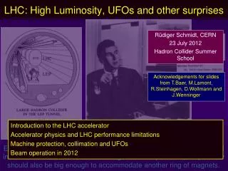
Machine Protection at LHC • MPS is complex and detailed, and lessons learned are expensive in time and money. • we can learn from LHC • The LHC will have more stored beam energy than any previous machine – 350 MJ • total energy is similar to a 747 at 1/3 of takeoff speed • the beam is so energetic, it is hard to deflect its trajectory quickly • the MPS is based on beam loss sensors • There are several (relatively simple) failure modes that result in the destruction of the entire machine (one of the rings) in one turn • 90 us. • the beam ‘cuts’ the vacuum chamber open along the mid-plane symmetry surface • LHC MPS makes extensive use of redundancy and machine ‘mode’ controls • allowing flexibility only when the power is low • Locks components (software mostly) at high energy
Failure modes • Subsystem failures can direct the beam outside its nominal path • failed dipoles - deflected trajectory • ‘run away’ movers • loss of accelerator RF – incorrect energy • Also: damping ring coherent beam instabilities or • increased generation of beam halo • Usually the control system will be aware of these conditions, but not always
Extreme beam deflections in the linac • Failed dipoles • Dipole strength limited to correct ~3 mm offsets of quadrupole misalignment at 500 GeV (Bdip/(∂B/∂x)) • this is ~10 σalignment • same dipole at low energies could correct for >30 times (500/15) that displacement • ⇒ beam outside of aperture • current limitation Imax(L) has to be built into hardware (firmware) • Mis-steering / mis-adjusted dipole correctors • Failed quadrupoles • need ~30 to fail before the aperture is hit, and beam becomes large before hitting the cavity surfaces
Failed RF phase control • linac ‘bandpass’ 50% • 60 degree phase advance /cell
Average power losses • Limiting average power loss is set by personnel radiation exposure concerns • typical limit for normal materials (Copper, Steel) ~ 100 W/m • (100 x the limit for protons) • 100 w is 1e-5 of the nominal power • this is extremely low compared to existing electron machines • beam dynamics can contribute to this loss, in addition to small mis-alignments etc. • 5 sigma (probably beyond present – day simulation code performance) • component heating from beam loss is also a concern, also at 100 W level • beam loss monitors with this degree of sensitivity are available.
Tuning up – Alignment example • In general following a startup, or at regular intervals • Controls will only indicate what sensors show • component alignment; sensor calibration or thermal drifts, sub-component deterioration may not be indicated • beam based checks, beam based tuning is required • steering, offset finding, emittance tuning, phase space checks • For example: Beam based alignment (BBA) • this process takes time; during which the machine is not integrating luminosity (TT) • typically takes ~ 100 pulses per focusing magnet; with ~5 different magnet currents • finds the offset between the magnet center and the BPM • 300 magnets: ~ 2 hours per linac • Beam based alignment works best if we start with good initial alignment • A major justification for the long downtimes
Time scale for repeating BBA • mechanical • forced disturbance (system bumped) • thermal cycling • ‘civil’ • concrete cracks • motion of the floor • electronic • replaced electronics • 300,000 hour MTBF (used in the availability simulation) • 2000 cavity BPM’s means one fails (and is replaced) per week • electronic gain drifts • imperfect calibration
LEP approach to BBA • Use sub-tolerance synchronous excitation • 17 Hz on quad windings • synchronous beam response proportional to actual beam offset • compare beam response observed to that predicted by offset estimated from nearby BPM • similar to ‘dither’ feedback used at SLC • requires extra precision margin • beyond that required for normal beam tuning
Using laser interferometers to connect beamline systems: Automatic alignment: 10 nanometer resolution possible • A sequence of nested tetrahedra; forms a sort of infinitely stiff truss • Information related via central triangle Ceiling node 1 Ceiling node 1 A B Floor node
main beam line LC Survey Problem Fiducial marker
SM beam internal FSI wall markers external FSI collider component Another idea: use a train of cars, locked to each other with laser interferometers Tunnel Wall LiCAS technology for automated stake-out process Reconstructed tunnel shapes (relative co-ordinates)
Developed for LHC ‘ATLAS’ Measurement Principle: Frequency Scanning Interferometry (FSI) Internal FSI System Dz. & Dx,Dy & Da,Db between cars Extrenal FSI System measures Wall marker location Straightness Monitor Dx,Dy & Da,Db between cars
Tune up process – beyond BBA Diagnosis and other procedures: • Tuning also will take place when none of the routine procedures are indicated • Everything seems to be ok, but the resulting beam is not satisfactory • diagnostics / instrumentation fulfill this role • Need low power beam for emittance tuning • relaxes MPS; may also release locks • Performance testing and checking procedures • Software data acquisition package for this: • Correlation ‘plot anything vs anything’ utility is required
Low power ILC • Single bunch operation of ILC may have no luminosity • ground motion and other instability will cause initial bunches to miss each other • 200 ms is long compared to typical drift amplitude rates • Thermal: 0.2e-3 degrees • vibration: 5 Hz amplitude > nm for macroscopic structures • Machine tuning will require independent study of emittance and power effects • we must be able to empirically prove the performance of one without the other • How many bunches are needed before an effective luminosity can be measured?
Number of bunches needed to establish collisions y angle scan y position scan: optimise signal in pair monitor y position FB: restore collisions within 100 bunches
Tables of tuning process - BDS • Showing • the time it takes per BDS procedure after 1) short downtime and 2) day-long downtime • continual BDS tuning required – the time it takes; associated interval and expected luminosity impact
Example table of tuning time: system wide • showing the tuning time required for all systems after a short downtime and after a day-long down with impact on luminosity
Tuning collimation - LHC example • much of the tuning time at SLC was adjusting collimators to reduce detector backgrounds • typical distances between collimators is large, position tolerances are tight and relative alignment tolerances are also tight • LHC will have primary, secondary and tertiary collimation • positions of the secondary/tertiary collimators will depend on the position of the primary and the trajectory between • the standard process of ‘touch’ and move back will be possible at LHC because of MPS • collimation tuning will require a special machine mode; with low power pseudo-benign beam
Sensitivity example: • In the BD system, the un-normalized vertical emittance is 4 fm-rad • with 40000 m beta, sigma_y~ 50 um • rms transverse momentum is 250 eV • The largest source of electric field in the BD is the beam itself • 250 V is quite small
Availability • Separate TUM=unscheduled maint and TR=recovery from MPS and tuning • These are directly related to the engineering / hardware effort • Subject to analysis to evaluate level of required performance and impact of basic design decisions: • One tunnel vs two • Damping rings in the same enclosure as linac • Typical components: • accelerator power supply MTBF 2e5 hours (at SR sources) • 1000 one failure per week • Dried electrolytic capacitors
Availability and large systems: • accelerators are some of the most complex machines ever built. • in ILC we have 1,000,000 components, with varying failure effects • there are 120 motors per RF unit (80000 motors total in the linac alone) • assume typical MTBF of 500,000 hours – two failures per hour • if each takes ½ hour to repair – there will be no operation • (neglecting recovery time) • We don’t expect to make perfect components with infinite lifetime • Redundancy is our strategy – exp for critical items • (e.g. many BPMs, but design so accel doesn't break when one is broken • (can mention difficulty of keeping lying BPMs from causing downtime due to steering and feedbacks), • energy headroom with energy feedbacks, • redundant regulators in power supplies, • hot spare water pumps). • recovery time may be extended due to thermal time constants
Availability evaluation - based on simulation • for simple systems, like a small accelerator, combine the single component performance, a simulation is not needed – spread sheet is ok. • for complex systems, with large scale sub-systems (DR, linac, positron), develop an ‘operations availability’ simulation • based on a machine description ‘deck’, which includes: • redundancy and ‘overhead’ • recovery • machine time management (machine development, use of repair personnel) • for example, in the one tunnel model, can only replace a limited number of klystrons per day. • failures that only degrade, as well as more serious failures that terminate operation • access constraints (e.g. the beam can be on in zone A with people in zone B) • this is used to determine civil layout constraints • actual MTBF and MTTR from existing machines (DESY, SLAC and Fermilab) • simulation is best suited for sequencing tasks • this is operations engineering • complex ‘management’ simulation code
Availability evaluation – • based on monte-carlo random event generation • have to perform several runs to get a ‘reliable’ result • includes operational requirements • machine development • entry requirements (radiation cool down) • limited number of people • used to compare alternatives • common errors may cancel
Klystron management • The linac contains spare klystrons, but these may be a long distance away from the one which just failed • complete readjustment of the linac may be required • including quadrupole strengths - to rematch the linac • this should be done quickly, to compensate for the expected (high) failure or fault rate • should be automated • within a pulse interval? or a few pulses? • need an accurate estimate of the energy along the linac and the gradients of the RF units involved in the exchange.
ATF2 project and redundancy • Target performance for ILC is far beyond present performance • 5 x for power supplies (10 x for SLAC power supply performance) • Solution is not to reduce MTBF of a given power supply, rather to reduce to zero the time to replace