Download
1 / 64
650 likes | 673 Views
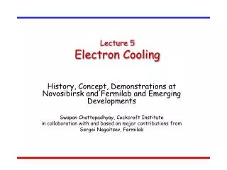
Fermilab Electron Cooling System. Nov 13, 2006 Sergei Nagaitsev. f. Fermi National Accelerator Laboratory. Proton source. CDF. Tevatron. Main Injector Recycler. D0. Antiproton source. Fermilab Complex. The Fermilab Collider is a Proton-Antiproton Collider operating at 980 GeV.

E N D
Fermilab Electron Cooling System Nov 13, 2006 Sergei Nagaitsev f Fermi National Accelerator Laboratory
Proton source CDF Tevatron Main Injector\ Recycler D0 Antiproton source Fermilab Complex • The Fermilab Collider is a Proton-Antiproton Collider operating at 980 GeV
Tevatron Program • Greatest window into new phenomena until LHC is on • 1500 collaborators, 600 students + postdocs • Critically dependent on luminosity • Doubling time a major consideration
Tevatron: key is luminosity Luminosity history for each fiscal year Integrated luminosity for different assumptions Top Line: all run II upgrades work Bottom line: none work ( pink/white bands show the doubling times for the top line)
Antiprotons and Luminosity • The strategy for increasing luminosity in the Tevatron is to increase the number of antiprotons • Increase the antiproton production rate • Provide a third stage of antiproton cooling with the Recycler • Increase the transfer efficiency of antiprotons to low beta in the Tevatron
Antiproton Production • 1x10⁸ 8-GeV pbars are collected every 2-4 seconds by striking 7x10¹² 120-GeV protons on a Inconel target • 8 GeV Pbars are focused with a lithium lens operating at a gradient of 760 Tesla/meter • 30,000 pulses of 8 GeV Pbars are collected, stored and cooled in the Debuncher, Accumulator and Recycler Rings • The stochastic stacking and cooling increases the 6-D phase space density by a factor of 600x106 • 8 GeV Pbars are accelerated to 150 GeV in the Main Injector and to 980 GeV in the TEVATRON
Recycler – Main Injector Recycler The Recycler is a fixed-momentum (8.9 GeV/c), permanent-magnet antiproton storage ring. The Main Injector is a rapidly-cycling, proton synchrotron. Every 1.6-3 seconds it delivers 120 GeV protons to a pbar production target. It also delivers beam to a number of fixed target experiments. Main Injector
Antiprotons flow (Recycler only shot) Keep Accumulator stack <100 e10 Increase stacking rate Transfer from Accumulator to Recycler Shot to TeV Tevatron 100 e10 Recycler Accumulator 2600e9 400 e10 200 e10
Beam Cooling in the Recycler The missions for cooling systems in the Recycler are: • The multiple Coulomb scattering (IBS and residual gas) needs to be neutralized. • The emittances of stacked antiprotons need to be reduced between transfers from the Accumulator to the Recycler. • The effects of heating because of the Main Injector ramping (stray magnetic fields) need to be neutralized.
Final goal for Recycler cooling: Prepare 9 (6 eV-s each) bunches for extraction
Performance goal for the long. equilibrium emittance: 54 eV-s Stochastic cooling limit MAX 36 bunchesat 2 eVs per bunch GOAL 36 bunchesat 1.5 eVs per bunch 20% lower
Recycler Electron Cooling • The maximum antiproton stack size in the Recycler is limited by • Stacking rate in the Debuncher-Accumulator at large stacks • Longitudinal cooling in the Recycler • Stochastic cooling only • ~140e10 for 1.5 eVs bunches (36) • ~180e10 for 2eVs bunches (36) Longitudinal stochastic cooling has been complemented by Electron cooling
How does electron cooling work? The velocity of the electrons is made equal to the average velocity of the ions. The ions undergo Coulomb scattering in the electron “gas” and lose energy, which is transferred from the ions to the co-streaming electrons until some thermal equilibrium is attained. Electron Gun Electron Collector Electron beam Storage ring 1-5% of the ring circumference Ion beam
Moving foil analogy • Consider electrons as being represented by a foil moving with the average velocity of the ion beam. • Ions moving faster (slower) than the foil (electrons) will penetrate it and will lose energy along the direction of their momentum (dE/dx losses) during each passage until all the momentum components in the moving frame are diminished. Foil vp p * represents rest frame
Electron cooling: long. drag rate • For an antiproton with zero transversevelocity, electron beam: 500 mA, 3.5-mm radius, 200 eV rms energy spread and 200 μrad rms angular spread Non-magnetized cooling force model Linear approx. Lab frame quantities
Electron cooling • Was invented by G.I. Budker (INP, Novosibirsk) as a way to increase luminosity of p-p and p-pbar colliders. • First mentioned at Symp. Intern. sur les anneaux de collisions á electrons et positrons, Saclay, 1966: “Status report of works on storage rings at Novosibirsk” • First publication: Soviet Atomic Energy, Vol. 22, May 1967 ”An effective method of damping particle oscillations in proton and antiproton storage rings”
Gerard K. O’Neill (1927-1992) • Was a professor of physics at Princeton University (1965-1985). He invented and developed the technology of storage rings for the first colliding-beam experiment at Stanford. He served as an adviser to NASA. He also founded the Space Studies Institute.
First Cooling Demonstration • Electron cooling was first tested in 1974 with 68 MeV protons at NAP-M storage ring at INP(Novosibirsk).
First cooler rings Europe – 1977 – 79,Initial Cooling Experiment at CERN M.Bell, J.Chaney,H.Herr, F.Krienen, S. van der Meer, D.Moehl, G.Petrucci, H.Poth, C.Rubbia– NIM 190 (1981) 237 USA – 1979 – 82,Electron Cooling Experiment at Fermilab T.Ellison, W.Kells, V.Kerner, P.McIntyre, F.Mills, L.Oleksiuk, A.Ruggiero, IEEE Trans. Nucl. Sci., NS-30 (1983) 2370;
Stochastic cooling • Stochastic cooling was invented by Simon van der Meer in 1972 and first tested in 1975 at CERN in ICE (initial cooling experiment) ring with 46 MeV protons. FNAL - 1980.
Fred Mills, one of the Fermilab physicists working on the electron cooling tests in 1980, writes:
Ee=300 keV Budker INP design 1 m 1 - electron gun; 2- main “gun solenoid”; 4 - electrostatic deflectors; 5 - toroidal solenoid; 6 - main solenoid; 7 - collector; 8 - collector solenoid; 11 - main HV rectifier; 12 - collector cooling system.
What makes the Fermilab system unique? • It requires a 4.36 MV DC power supply. We have chosen a commercially available electrostatic accelerator. As a consequence we had to develop several truly new beamline, cooling, and solenoid technologies: • Interrupted solenoidal field: there is a magnetic field at the gun cathode and in the cooling section, but no field in between. It is an angular-momentum-dominated transport line; • Low magnetic field in the cooling section: 50-150 G. Unlike low-energy coolers, this results in non-magnetized cooling – something that had never been tested before; • A 20-m long, 100-G solenoid with high field quality
History of commissioning • March 2005 • For the first time, 5 MV in the Pelletron (at the Recycler setup) • July 2005 • Imax = 0.4 A; I = 0.2 A is stable enough • First cooling of 8 GeV pbars • September 2005 • All shots are e-cooled • Electron beam is used at 50 – 100 mA and is stable
High-energy (relativistic) electron cooling • Novosibirsk, 1987: Tested a prototype for a 1-MV, 1-A electron beam system. • Fermilab, 1983: D. Cline et al., “Intermediate energy electron cooling for antiproton sources using a Pelletron accelerator” • For a pulsed electron beam in a Pelletron the beam quality is adequate for electron cooling • Fermilab, UCLA, NEC, 1989: Tested a 2-MV, 0.1-A recirculation system with a Pelletron. • Fermilab, IUCF, NEC, 1995: started to work on a 2-MV Pelletron again. • Fermilab, 1999: Purchased a 5-MV Pelletron • Fermilab, 2004: Installed a 5-MV Pelletron in the Recycler
The R&D program • 20-Mar-01- Fist time HV on both tubes • 28-Dec-01 - 0.6 A in the short beam line • 18-Nov-02 - Imax=1.7 A; beginning of a shutdown • 17-Jul- 03 - DC beam recirculated through the full-scale line • 30-Dec-03- 0.5 A DC beam • 29-May-04- 0.1 A beam with required beam properties in the cooling section
Pelletron Disassembly/Move • Pelletron at Wide Band Lab Before Disassembly (5/04) • 1.5 Months to Disassemble • Lower Half of Pelletron Being Transported to MI31 • All Components Transported 3-Miles Across the Laboratory
Lab Wide Shutdown to install electron cooling • Before and After Pictures of E-Cool Section of MI Tunnel • 13-Week Shutdown • Modified MI Utilities, Removed Recycler Section, Installed all Beam Lines • Lab-Wide Effort
Electron beam design parameters • Electron kinetic energy 4.34 MeV • Uncertainty in electron beam energy 0.3 % • Energy ripple 500 V rms • Beam current 0.5 A DC • Duty factor (averaged over 8 h) 95 % • Electron angles in the cooling section (averaged over time, beam cross section, and cooling section length), rms 0.2 mrad All design parameters have been met
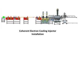
Electron cooling system setup at MI-30/31 Pelletron (MI-31 building) Cooling section solenoids (MI-30 straight section)
Specific features • Energy recovery scheme • Transport of the beam with a large effective emittance • Low magnetic field in the cooling section • Sharing the tunnel with the Main Injector
Simplified electrical schematic of the electron beam recirculation system For I= 0.5 A, I= 5 A: • Beam power 2.15 MW • Current loss power 21.5 W • Power dissipated in collector 2.5 kW The beam power of 2 MW requires the energy recovery (recirculation) scheme
Tube current, 2µA/div Pelletron current, 10µA/div Anode current, 2µA/div Collector ion pump current Current losses Current losses have to be low • Losses to the tube electrodes should not exceed few µA to avoid overvoltage • Losses at the ground should not exceed few tens of µA to avoid damaging the vacuum chamber Gun closes Beam current, 0.1A/div Typical plot of losses as functions of the beam current. dI/I =(1.2-1.5)·10-5.
Bcz = 90 G Rcath = 3.8 mm Bcz = 105 G Rbeam = 3.5 mm Bz = 0 R = 2 -10 mm (normalized) (normalized) (normalized) Beam line Cathode Cooling section Effective emittance Figure of merit: magnetic flux inside the beam in the cooling section = effective emittance outside the longitudinal magnetic field Low energy portions of the acceleration and deceleration tubes have to be immersed into a longitudinal magnetic field. A 3D beam line has to provide an axially symmetrical beam transformation.
Beam quality • Cooling force depends on rms electron angle in the cooling section (averaged over time, beam cross section, and cooling section length) • Contributions come from • Temperature • Aberrations • Beam motion (vibrations in the Pelletron, MI ramps) • Drift velocity • Dipole motions caused by magnetic field imperfections • Envelope scalloping Cooling section
Neighborhood with the Main Injector • Magnetic fields of busses and MI magnets in the time of ramping causes an extensive motion of the electron beam (up to 0.2 mm in the cooling section and up to 2 mm in the return line) • MI radiation losses sometimes result in false trips of the ECool protection system MI bus current 1mm X Y MI loss 2 sec Electron beam motion and MI losses at R04 location in the time of MI ramping. 0.55 Hz oscillation is due to 250 V (rms) energy ripple.
Low magnetic field in the cooling section • Cooling is not magnetized • The role of the magnetic field in the cooling section is to preserve low electron angles, Transverse magnetic field map after compensation. Bz = 105 G. • A typical length of B perturbation, ~20 cm, is much shorter than the electron Larmor length, 10 m. Electron angles are sensitive to , not to B . Simulated angle of an 4.34 MeV electron in this field give r.m.s angle of 50 rad.
Cooling in barrier buckets Keep momentum spread constant, compress the bunch length by moving the rf barrier Simulation (MOCAC) of electron cooling + IBS, 500 mA e-beam, 600x1010 pbars 100 eV-s 50 eV-s 30 minutes
Electron angles in the cooling section *Angles are added in quadrature
Example for the longitudinal friction force • For an antiproton with zero transversevelocity, electron beam (uniform): 500 mA, 3.5-mm radius, 200 eV rms energy spread and 200 μrad rms angular spread Note: Units have been changed to more ‘convenient’ units Linear approx.
Longitudinal cooling force measurements - Methods • Two experimental techniques, both requiring small amount of pbars (1-5 × 10¹⁰), coasting (i.e. no RF) with narrow momentum distribution (< 0.2 MeV/c) and small transverse emittances (< 3 p mm mrad, 95%, normalized) • ‘Diffusion’ measurement • For small deviation cooling force (linear part) • Reach equilibrium with ecool • Turn off ecool and measure diffusion rate • Voltage jump measurement • Reach equilibrium with ecool • Instantaneously change electron beam energy • Follow pbar momentum distribution evolution
Traces (from left to right) are taken 0, 2, 5, 18, 96 and 202 minutes after the energy jump. Example: 500 mA, nominal settings, +2 kV jump (i.e. 3.67 MeV/c momentum offset), on axis ~3.7 MeV/c 2.8 × 10¹⁰ pbar 3-6 p mm mrad
Extracting the cooling (drag) force Evolution of the weighted average and RMS momentum spread of the pbar momentum distribution function 15 MeV/c per hour