Download
1 / 19
190 likes | 407 Views
Multi-core Systems and Coherence Hierarchies. Coherence hierarchy issues Several architecture specific implementations Design complexity Complex hierarchy state encodings Many more transient states Solution: Coherence Realm* Encapsulation

E N D
Multi-core Systems and Coherence Hierarchies • Coherence hierarchy issues • Several architecture specific implementations • Design complexity • Complex hierarchy state encodings • Many more transient states • Solution: Coherence Realm* Encapsulation • Define communication interface between users and monitors • Enables layering of coherence • Enables heterogeneity within a protocol
Manager-Client Pairing (MCP)* *J. G. Beu, M. C. Rosier and T. M. Conte, “Manager-Client Pairing: A Framework for Implementing Coherence Hierarchies,” Proceedings of the 44th Annual International Symposium on Microarchitecture (MICRO-44), (Porto Alegre, Brazil), Dec., 2011.
Division of Labor • Client Agent (think cache) • Permission holder (Coherence State) • Obtains permission via acquire requests • Act as a gateway in hierarchical coherence (see algorithm) • Manager Agent (think directory) • Monitor of coherence realm • Records sharers, owner, etc. • Manages permission propagation • Process acquire requests • Allocates/de-allocates permissions to/from clients • Handles external requests from other realms
Special Functions • Client: Eviction Permissions? • Evict_P and GetEvict • Why? What if in M/O state? • Directory is making assumptions about client’s role • That client will fwd data to other caches • Client needs to inform directory before giving up ownership • Manager: Downgrade (DwnInval and DwnRead) • Realm A has in the M state • Realm B asks for permission • Asks for write permission, A needs to become invalid • Asks for read permission, A only needs to give up exclusivity but can keep a copy
Cache Model and Interface A cache model has two interfaces: The processor-cache interface and The cache-network interface. The Processor-Cache Interface On the process-cache interface, the processor sends requests to the cache and the cache sends responds back. Message from processor The processor model's request is supposed to implement the following two functions: 1. get_addr(). This function returns a 64-bit integer that is the memory address for which the cache request is made. 2. is_read(). This function returns true if the request is a read(load), and false if it is a write(store). The cache model's event handler for the processor-cache interface should be a templated function similar to the following: template<typenameT> voidmy_cache_req_handler(int, T*); The templated type T is the type of the request from the processor. Message to processor Currently it is required that the cache model sends back to the processor the same data type that it gets from the processor. Therefore, if the processor sends type T to the cache, then the cache must respond with the same type T.
Cache-Network Interface If the cache model is not directly connected to the interconnection network, it can send/receive its own data type. If it is connected to the network, then it should send/receive manifold::uarch::NetworkPacket The cache model's own data should be serialized and stored in the member variable (an array) data of NetworkPacket. The simplest way to do this is just using byte-wise copy: MyDataType* obj; NetworkPacket* pkt = new NetworkPacket(); *((MyDataType*)pkt->data) = obj; A cache model could send two types of messages over the network: 1. Cache-to-cache messages, such as coherence messages. 2. Cache-to-memory messages. Both are carried by NetworkPacket.
Cache-Network Interface…. A cache model also receives two types of messages: from another cache or from memory. The event handler for its network input should be a templated function as follows: template<typenameT> voidmy_net_handler(int, manifold::uarch::NetworkPacket*); where the template parameter T is the data type from memory controller and is supposed to define the following two functions: get_addr(). This functions returns a 64-bit integer that is the memory address for which the cache request is made. is_read(). This function returns true if the request is a read(load), and false if it is a write(store). Pseudo code for the cache model's event handler for the cache-network interface is given below: template<typenameT> voidmy_net_handler(int, manifold::uarch::NetworkPacket* pkt) { IF pkt->type == coherence message THEN MyCohMsg* coh = new MyCohMsg(); *coh = *((MyCohMsg*)(pkt->data)); process(coh); ELSE IF pkt->type == memory message THEN T objT = *((T*)(pkt->data)); MyMemMsg* mem = new MyMemMsg; Set the member values of mem with objT; process(mem); END IF }
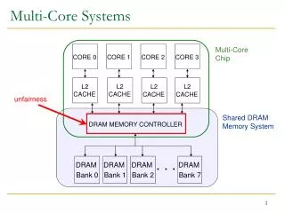
CaffDRAM Overview CaffDRAM is a cycle accurate DRAM timing simulator. This simulator is JEDEC compliant and models various timing parameters pertaining to resource contention within the DRAM main memory. Processor Cache Memory System Integrated DDRx Memory Controller Memory Bus
Memory Organization Memory Controller CH 1 CH2 CH N RANK 1 RANK 2 RANK 3 RANK 4 *A Single DIMM Module may consist of “one” or “two” Ranks depending upon its pin configuration. Each Side of a DIMM module is one “RANK” . A single “RANK” usually consists of 8 “x8” chips corresponding to a Data Bus width of 64 bits
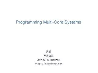
DRAM Scheduling Command Generator DRAM Configuration DRAM Policies Channel Bus Scheduler Delay Parameters Request Queue Incoming Request SPD (Serial Presence Detect) Rank Scheduler Bank Scheduler
Rank I/O Devices Contention Modeling Rank Scheduler responsible for “I/O Device” resource contention * On every “Read” multiple internal bursts are required to form aLonger burst on the data bus. * On every “Write” data direction is reversed and these devicesact as buffers for incoming data. I/O Devices in use = Busy for “t_CCD” cycles t_CCD = 2 beats for DDR = 1 memory cycle t_CCD = 4 beats for DDR2 = 2 memory cycles t_CCD= 8 beats for DDR3 = 4 memory cycles Rank I/O Device Single Rank
Bank Contention Modeling Bank Scheduler responsible for “Multiple Row Conflict” within a bank An Active Row A Bank when accessed on a memory request activates a row which fills in the “sense amplifiers” with data from that row This operation takes time = t_RCD After time t_RCD, data from the “addressed columns” may be accessed. After time = t_CAS (a.k.a. t_CL) data is placed on the Channel Data Bus Sense Amplifiers (Each Bank has a set of sense Amplifiers shared by each row in a bank)
Bank Contention Modeling…. Previously Active Row Newly accessed row within same bank causing resource conflict Row Activation = Bank busy for “t_RAS” cycles Bank Precharge = Bank busy for “t_RP” cycles *If a subsequent access is made to the same open row, the request can proceed immediately after the first without having to wait for t_RAS. In case of a different row the timing protocol must be followed
CaffDRAM Interface * A memory controller has one interface: the memory controller-network interface. It sends/receives NetworkPacket which carries the memory requests and responses. * The requests are defined in the cache model, therefore, the memory controller does not have the definition. For this reason, the event handler should be a template function as follows: template<typenameT> void handler(int, manifold::uarch::NetworkPacket* pkt) { T* request = (T*)(pkt->data); boolisRead = request->is_read(); uint64_t addr = request->get_addr(); ... }
CaffDRAM Interface…. As can be seen, the request from cache is supposed to implement the following two functions: get_addr(). This functions returns a 64-bit integer that is the memory address for which the cache request is made. is_read(). This function returns true if the request is a read(load), and false if it is a write(store). For response, the memory controller model can reuse the data type of the cache's requests, or it can define its own. In the latter case, the data type must also support the same two functions above. Message Types The responses sent by the memory controller model use a message type (the type filed of NetworkPacket) that should be different from other message types. Therefore, the memory controller developer should not hard code the message type value. Instead, the type should be set in the constructor or an access function. The system model builder is responsible for setting the types.