Download
1 / 3
30 likes | 206 Views
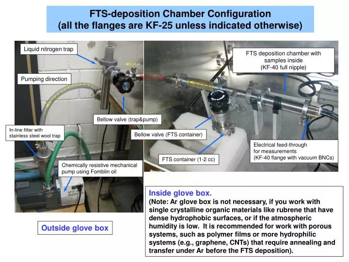
FTS-deposition Chamber Configuration (all the flanges are KF-25 unless indicated otherwise). Liquid nitrogen trap. FTS deposition chamber with samples inside (KF-40 full nipple). Pumping direction. Bellow valve (trap&pump). In-line filter with stainless steel wool trap.

E N D
FTS-deposition Chamber Configuration (all the flanges are KF-25 unless indicated otherwise) Liquid nitrogen trap FTS deposition chamber with samples inside (KF-40 full nipple) Pumping direction Bellow valve (trap&pump) In-line filter with stainless steel wool trap Bellow valve (FTS container) Electrical feed-through for measurements (KF-40 flange with vacuum BNCs) FTS container (1-2 cc) Chemically resistive mechanical pump using Fomblin oil Inside glove box. (Note: Ar glove box is not necessary, if you work with single crystalline organic materials like rubrene that have dense hydrophobic surfaces, or if the atmospheric humidity is low. It is recommended for work with porous systems, such as polymer films or more hydrophilic systems (e.g., graphene, CNTs) that require annealing and transfer under Ar before the FTS deposition). Outside glove box
Optimized procedure for deposition of FTS self-assembled monolayer on rubrene: For the original paper, please see: M. F. Calhoun et al.,Nature Mater. 7, 84 (2008). 1. Place samples in the FTS deposition chamber properly. Connect the monitoring sample (with contacts and wire leads) to the electrical feed-through connectors and check the connectivity. Start the program monitoring sample’s conductivity. Assemble the rest of the system as shown in the figure. 2. Make sure that the FTS container valve is closed. Load an appropriate amount of liquid FTS (Sigma Aldrich #448931) to the FTS container: a few drops for a short-time treatment to achieve a partial coverage and somewhere between 1/3 and 1/2 of the container for a long treatment to get full coverage. Attach the container to the deposition system properly as shown in the figure. 3. Turn on the mechanical pump and open the liquid nitrogen trap & pump valve (but not the FTS container valve). Pump the deposition chamber for 40 minutes. 4. Fill the cold trap with liquid nitrogen and wait for another 10 minutes. 5. Slowly open the FTS container valve and leave it open for 1 min, while the mechanical pump is pumping the chamber through the cold trap. This removes the small amount of air trapped in the FTS container and activates rapid evaporation of FTS molecules filling the chamber with FTS fume. 6. After 1 min, close the liquid nitrogen trap & pump valve. 7. Turn off the pump and disassemble the liquid nitrogen trap. Leave all parts of the trap under a well ventilated hood. Clean all parts after they reach room temperature. 8. When FTS deposition is done (which you monitor in-situ by conductivity measurements), close the FTS container valve. 9. Assemble the thoroughly cleaned liquid nitrogen trap and connect it to the system as shown in the figure. Turn on the pump and wait for 10~20 minutes, then add liquid nitrogen and wait for another several minutes. 10. Slowly open the liquid nitrogen trap & pump valve and pump the deposition chamber for 30 minutes to remove the FTS fumes and FTS accumulated on the inner walls of the chamber. Keep sufficient amount of liquid nitrogen while pumping (refill the trap when necessary). 11. Close the liquid nitrogen trap & pump valve. 12. Turn off the pump and disassemble the liquid nitrogen trap. Leave all parts of the trap under a well ventilated fume hood. Clean all parts again after they reach room temperature. 13. Stop the electrical measurements. Carefully open the FTS chamber to the atmosphere (or Ar, if you work under Ar). Remove samples. 14. Remove the FTS container and clean it with acetone. 15. Reassemble the deposition system, including the FTS container and the cold trap. 16. Pump the chamber for 10 minutes with both valves open. Close both valves and turn off the pump. Store the empty chamber in this closed condition when not in use to slow down degradation of parts.
Important notes: 1. For high-quality full-coverage FTS deposition, cleaning all the parts on the right side of the PVC hose (see the figure), including O-rings, chamber parts, the FTS container valve and the electrical feed-through connectors, is recommended each time before deposition. Clean the PVC hose as well if necessary. 2. Check the base pressure of the clean, dry and fully assembled empty chamber (w/o FTS or samples) regularly before each treatment. FTS deposition failure is usually due to a poor vacuum. In our experience, the base pressure in a cleaned and fully assembled chamber of our size is 7 - 8 10-4 Torr after a 40-min pumping plus adding liquid nitrogen to the trap. After a few uses, the pressure becomes 1-2 10-3 Torr, which in our experience is sufficient for a high-quality FTS deposition. Condition of the pump oil and the stainless steel wool trap should be checked regularly. Do not use a vacuum gauge for pressure measurements in-situ while doing FTS deposition, because it may cause corrosion of the gauge. 3. When not in use, keep the deposition chamber fully assembled and under vacuum. 2D = 1.2·10-5 S/ Exposure to FTS vapor Typical current as a function of time curve recorded during the FTS deposition for a 2-probe pristine rubrene sample. Voltage applied is V = 1 V, distance between the contacts L = 3 mm, width of the crystal W = 1 mm. Same data on a semi-Log scale