Download
1 / 32
320 likes | 442 Views
ECE-L304 Lecture 7. Revisit Step 6, Begin Final Step. Extended Lab Hours. Eric will be available for extended lab hours starting next week. Week 9 and 10 Monday 12pm-4pm Wednesday 11am-5pm Friday 9am-4pm Finals Week Tuesday 12pm-4pm Wednesday 12pm-4pm

E N D
ECE-L304 Lecture7 Revisit Step 6, Begin Final Step
Extended Lab Hours • Eric will be available for extended lab hours starting next week. • Week 9 and 10 • Monday 12pm-4pm • Wednesday 11am-5pm • Friday 9am-4pm • Finals Week • Tuesday 12pm-4pm • Wednesday 12pm-4pm • Unless discussed with me otherwise all lab reports and disassembled boards are due Wednesday September 3rd by 4pm!!!! ECE-L304 Lecture 7
Second Quiz • Second quiz will go online Friday of week 9 and close Friday of week 10. • I will be looking for cheating, perhaps in a sneaky manner • I will discuss exact topics in final lecture, will primarily focus on details of the project ECE-L304 Lecture 7
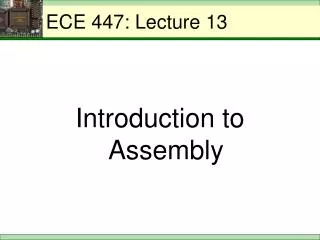
Project CircuitThis Week 8 8 ADC DAC RAM 17 2 Address Gen R/W Control Clock ECE-L304 Lecture 7
Step 6 Prelab • Analyze the control circuit used in the Step 4 simulation from Address Generator Q TC = Terminal Count Q ECE-L304 Lecture 7
Step 6 Prelab • Subset of NEC RAM (uPD431000A) Control Table:We also have CS1 and CS2 to deal with WE OE Mode L X WRITE H L READ Active Low Logic ECE-L304 Lecture 7
Step 6 • Part 1 • Assemble the 16-bit address generator • Place the circuitry according to your floorplan • Use the 555 counter as the clock for now • Design and build a circuit that will provide a 17th bit • This step is required to get full hardware credit • Confirm functionality using the logic analyzer ECE-L304 Lecture 7
Step 674LS590 Description • There are several methods in which to operate and create 17 bit counter. • Controlling Count Enable with RCO • Counting RCO • Separating Count Clock and Register Clock • Controlling Count Enable with RCO is most common configuration with digital counters ECE-L304 Lecture 7
G G LO LO CCLK CCLK CLK CCLKEN CCLKEN RCO RCO A7 A7 RCLK RCLK A7 A15 A6 A6 CCLR CCLR A6 HI HI A14 A5 A5 A5 A13 A4 A4 A4 A12 A3 A3 A3 A11 A2 A2 A2 A10 A1 A1 A1 A9 A0 A0 A0 A8 Step 6Cascaded 74LS590 Chips ECE-L304 Lecture 7
Step 674LS590 Description • “Both the counter and register clocks are positive edge triggered. If the user wishes to connect both clocks together, the counter state will always be one count ahead of the register.” ECE-L304 Lecture 7
Step 6 • Part 1 • Add two AND gates between clock output and counter input • This is for testing purposes only - in your circuit this delay would be between CLK and RAM WE • Observe time delay between incoming and exiting clock pulses on the logic analyzer • Calculate the delay per gate ECE-L304 Lecture 7
Step 6 • Part 2 • Assemble the control circuitry you designed in the prelab • Place and wire the circuitry according to your floorplan • Connect RAM CE1 and CE2 to the proper logic levels • Confirm functionality using the logic analyzer ECE-L304 Lecture 7
Board Center Connectors • ADC Control • CS_, RD_, WR_, INTR_ • Power, GND • RAM Control • CE1_, CE2, OE_, WE_ • RAM Addresses • A16 - A0 ECE-L304 Lecture 7
Step 6 Deliverables • Have functionality of address generator and control circuit checked by TA • Step 6 Prelab Worksheet • Introduction • Verified address generator and RAM control circuit functionality • Include in your report well labeled screen captures from the scope/logic analyzer which verify the functionality ECE-L304 Lecture 7
Step 6 Deliverables • Results of AND gate delay test • Document with a screen capture • Conclusions • Comment on your observations ECE-L304 Lecture 7
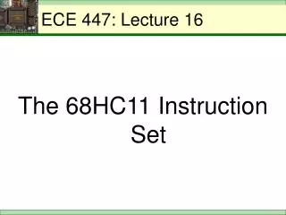
8 8 ADC DAC RAM ? 2 17 Clock ADC Control R/W Control Address Gen Project CircuitStep 7 Blocks ECE-L304 Lecture 7
Step 7 Goals • Control the ADC • Modify the RAM control according to the chosen timing strategy • Add the RAM chip to the circuit • Optimize performance • Test the circuit ECE-L304 Lecture 7
System Timing • Last lecture we looked at the WRITE cycle timing for several scenarios • Now we need to design and implement the READ cycle timing • Implement ADC timing • Modify RAM control timing ECE-L304 Lecture 7
ADC Control • Get the ADC off-line • Our acquisition system has only one data bus, which is shared by the ADC and the DAC • We have to take the ADC off-line during the RAM READ cycle so we do not have the ADC and RAM writing to the bus simultaneously ECE-L304 Lecture 7
ADC Control • Specify when to get new data • Take the ADC out of its current free-running mode • In free-running mode, the INTR pin signal initiates a new data conversion when it falls • Synchronize the system • Generate a new memory address every clock cycle • Put new data on the bus every clock cycle ECE-L304 Lecture 7
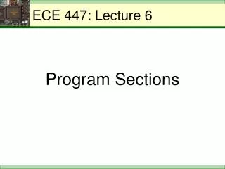
20 1 CS 2 19 RD 3 18 WR DB0 4 17 CLK IN • • • • 5 16 INTR 6 15 7 14 8 13 9 12 10 11 DB7 ADC ControlADC0804 Pins CS = Chip Select RD = Read WR = Write INTR = Interrupt ECE-L304 Lecture 7
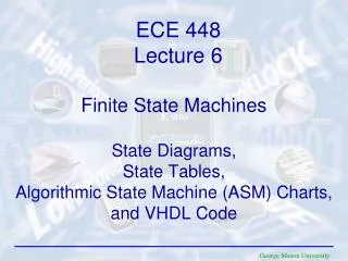
1 20 CS 2 19 RD 3 18 WR DB0 4 17 CLK IN Start • • • • 5 16 INTR 6 15 7 14 8 13 9 12 10 11 DB7 ADC ControlFree-Running Circuit CS = Chip Select RD = Read WR = Write INTR = Interrupt ECE-L304 Lecture 7
1 20 CS 2 19 RD 3 18 WR DB0 4 17 CLK IN Start • • • • 5 16 INTR 6 15 7 14 8 13 9 12 10 11 DB7 ADC ControlFree-Running Circuit • While CS is low, acquisition starts whenever WR drops • How can this happen? • Start switch is grounded • INTR output falls ECE-L304 Lecture 7
The first task is to make sure the 555 clock and the ADC internal clock are coordinated.
Final Grading of Circuit • Points will be allotted depending on functionality of circuit • Bandwidth • Address Generator • RAM/ADC Control • Timing • Playback • Construction ECE-L304 Lecture 7
Extra Prelab For Step 7 • Please print out and turn in 2 copies of grading page describing design goals for the project before next Monday • Sheets must be turned in to eric • Commonwealth 304- slide under door if no answer • Mailbox on 4th floor next to ECE office (gallo) ECE-L304 Lecture 7