Download
1 / 16
160 likes | 288 Views
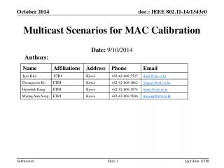
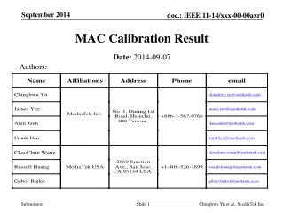
MAC calibration results. Date: 2014-07. Authors:. Contribution [1][2] define the simulation scenarios and evaluation method for MAC system calibration This contribution provides preliminary results on MAC calibration Test 1: MAC overhead test Test 2: Deferral test

E N D
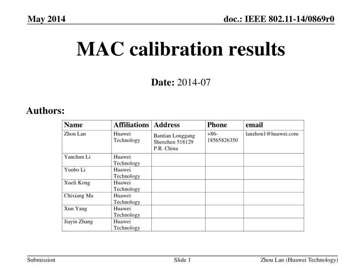
MAC calibration results Date: 2014-07 Authors: Zhou Lan (Huawei Technology)
Contribution [1][2] define the simulation scenarios and evaluation method for MAC system calibration • This contribution provides preliminary results on MAC calibration • Test 1: MAC overhead test • Test 2: Deferral test • For test 4, we found the test case violates the basic 802.11ac MAC behavior, therefore we propose to modify the test case to fulfill the calibration purpose Summary
AP1 • Assumptions: • PER is 0 • Parameters: • MSDU length:[0:500:2000Bytes] • RTS/CTS OFF • MCS = [0,8] ( to clarify, run a sweep over MSDU length once for MCS 0, and once for MCS 8. Test 1a: MAC overhead w/out RTS/CTS-Simulation Parameter- STA 1 AP1
AP1 Test 1a: MAC overhead w/out RTS/CTS-Check Points- s 0.012128065 _1_ MAC --- 1 cbr 3016 [54 0 1 0] Check point1 (CP1) r 0.015896097 _0_ MAC --- 1 cbr1472 [0 0 1 0] Check point2 (CP2) • r 0.015896097 _0_ MAC --- 2 cbr1472 [0 0 1 0 Check point2 (CP2) • s 0.015912097 _0_ MAC --- 0 ACK 32 [0 1 0 0] Check point3 (CP3) • r 0.015980129 _1_ MAC --- 0 ACK 32 [0 1 0 0] Check point4 (CP4) • s 0.016122129 _1_ MAC --- 3 cbr 3016 [54 0 1 0] Check point5 (CP5)
AP1 Test 1a: MAC overhead w/out RTS/CTS-Throughput Performance-
AP1 • Assumptions: • PER is 0 • Parameters: • MSDU length:[0:500:2000Bytes] • RTS/CTS ON • MCS = [0,8] ( to clarify, run a sweep over MSDU length once for MCS 0, and once for MCS 8. Test 1b: MAC overhead w RTS/CTS -Simulation Parameter- STA 1 AP1
AP1 Test 1b: MAC overhead w RTS/CTS -Check Points- s 0.012229123 _1_ MAC --- 0 RTS 20 [f58 0 1 0] Check point1 (CP1) • r 0.012281154 _0_ MAC --- 0 RTS 20 [f58 0 1 0]Check point2 (CP2) • s 0.012297154 _0_ MAC --- 0 CTS 14 [f1c 1 0 0] Check point3 (CP3) • r 0.012341185 _1_ MAC --- 0 CTS 14 [f1c 1 0 0] Check point4 (CP4) • s 0.012357185 _1_ MAC --- 1 cbr 3016 [0 0 1 0] Check point5 (CP5) • r 0.016125216 _0_ MAC --- 1 cbr 1472 [0 0 1 0] Check point6 (CP6) • r 0.016125216 _0_ MAC --- 2 cbr 1472 [0 0 1 0] Check point6 (CP6)
AP1 Test 1b: MAC overhead w RTS/CTS -Throughput Performance-
AP1 AP 2 AP1 STA 2 STA 1 (AP1 and STA2 are essentially co-located) • Assumptions: • devices are within energy detect range of each other. • When AP1 and AP2 start to transmit on the same slot, both packets are lost (PER= 100%). Otherwise packets get through 100%. PER=0 % • Parameters: • MSDU length:[0:500:2000Bytes] • RTS/CTS [ OFF, ON] • MCS = [0, 8] Test 2a: Deferral Test 1-Simulation Parameters-
AP1 Test 2a: Deferral Test 1-Throughput Performance-
AP1 • Assumptions: • AP1 and AP2 can not hear each other. ( ever) • If MPDUs from AP1 and AP2 overlap, they both fail with 100% probability • If an MPDU from AP1/AP2 is interference free, it succeeds with 100% probability. • Parameters: • MSDU length:[0:500:2000Bytes] • RTS/CTS [ OFF, ON] • MCS = [0, 8] Test 2b: Deferral Test 2-Simulation Parameters- STA 2 AP 2 AP1 STA 1
AP1 Test 2b: Deferral Test 2-Throughput Performance-
AP1 AP 2 AP1 STA 2 STA 1 (AP1 and STA2 are essentially co-located) • Assumptions: • All devices are within energy detect range of each other. • When AP1 and AP2 start to transmit on the same slot, both packets are lost (PER= 100%). Otherwise packets get through 100%. PER=0 % • APs send single MPDU, but sets NAV to txop= 4 ms • APs should defer due to NAV setting.. Test 4: NAV deferral Source from [1] • According to 802.11ac, STA doesn't stop transmitting frame in an allocated TXOP, sending one single frame and leaving the rest of TXOP open doesn’t look like a reasonable assumption • Propose to change the single MPDU to MPDUs
[1] 11-14-0621-04-00ax-simulation-scenarios [2] 11-14-0571-02-00ax-evaluation-methodology Reference
Test1a + Test1b • Simulation results and theoretical calculation matches