Download
1 / 11
120 likes | 279 Views
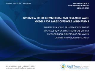
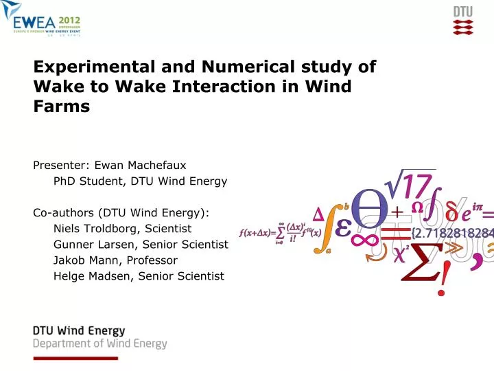
Experimental and Numerical study of Wake to Wake Interaction in Wind Farms. Presenter: Ewan Machefaux PhD Student, DTU Wind Energy Co-authors (DTU Wind Energy): Niels Troldborg , Scientist Gunner Larsen, Senior Scientist Jakob Mann, Professor Helge Madsen, Senior Scientist.

E N D
Experimental and Numerical study of Wake to Wake Interaction in Wind Farms Presenter: Ewan Machefaux PhD Student, DTU Wind Energy Co-authors (DTU Wind Energy): NielsTroldborg, Scientist Gunner Larsen, Senior Scientist Jakob Mann, Professor Helge Madsen, Senior Scientist
1 – Introduction • Goal: • continuation of previous CFD study: Numerical Simulations of Wake Interaction between Two Wind Turbines at Various Inflow Conditions, N. Troldborg et al. 2010 • aim to contribute to the overall understanding of two interacting wakes • improve/extend existing the Dynamic Wake Meandering model from single wake to multiple wakes • Methodology: • one-to-one mapping of experimental results on numerical predictions of interacting wakes.
2 - Experimental approach: Tjæreborg site • TjæreborgEU-TOPFARM full scale LIDAR based measurements campaign • Five NM80-2MW and three V80-2MW (Dong Energy A/S - Vattenfall AB) • WT3 LiDAR mounted • QinetiQ ZephIR Continuous Wave Lidar • M1: 93m mest mast • 2 selected double wake directions • 2 timeseries analyzed WT4 M1 WT3 WT1 WT2
2 - Experimental approach: wake resolving General methodology for wake resolving Scanning pattern of CW LiDAR Computation from Doppler Spectra to line-of-sight velocity Ulos Filtering of bad measurements Discretization: 2 x 10 m² (cell center in red) Projection due to tilting and panning of the laser beam WT3 WT3
3 – Numerical approach: computational set up Key features: • EllipSys3D flow solver ; Actuator Line Technique ; Large Eddy Simulation • ABL modeled: • shear: steady body forces computed and applied in the entire domain • synthetic turbulent fluctuations, Mann model • Constant RPM, constant pitch, no yaw • 2 grids (large spacing:3.98M & low spacing:2.95M cells) • Unsteady computations: 10 minutes flow field statistic Farfieldvelocity (4th grid level shown) (960m, 960m, 1496m) Appliedwithdesiredwindshear Unsteadyconvectiveconditions St. Turbulence introduced LiDAR plane WT2 WT3 Eq. Wallno slip Stretched Equidistant coarse Equidistant fine (spacing 0.04R) Stretched
4 – Results: case 1 with large spacing 2.5D downstream; ≈5.5D turbine spacing; U0=8.5 m/s Streamwise wake velocity at hub height Streamwise wake turbulence level at hub height apparent offset
4 – Results: case 2 with low spacing 2.5D downstream;≈3D turbine spacing; U0=7.24 m/s Streamwise wake velocity at hub height Streamwise wake turbulence level at hub height apparent offset Quantification of the offset? Cross correlation study: ≈ 5m at 200m 1.5deg error
4 – Conclusions • Good agreement (high correlation) on organized flow structure part of the wake • Offset consequence of yaw/mounting misalignment • … need to overcome the present limitations • 10min averaged quantities limitation in time and spatial resolution in the measured wake • Only in the fixed frame of reference • Only one downstream cross section • No knowledge of the single wake flow field upstream of the second rotor • New merged wake experiment (April 2012)
5 - Future merged wakes experiment DSF FlowCenter April 2012 Nordtank 500kW Tellus 95kW 36m 29m ~4.3 x Dtellus= 80m ~4.9x DNordtank= 200m WindScanner CW LiDAR Wind scanner 400pts/sec CW LiDAR 348pts/sec Nordtank D=41m 1xD ~35x12m 3.9xD ~140x50m
5 – Future merged wakes experiment • Future experiment strengths: • high spatial and time resolution • several planes can be scanned at a time • turbulence structures, meandering, expansion and recovery of the wake can be investigated • the use of 2 LiDARS will enhance knowledge of the inflow to the downstream turbine
Acknowledgment: Dong Energy, DSF Flow Center, EU-TOPFARM Thank you for your attention