Download
1 / 26
260 likes | 401 Views
WORKSHOP 4 PIPE CRUSH ANALYSIS. Move 2 in the -Y. R=4. Rigid Body 2. Pipe. R=3. Rigid Body 1. Move 2 in the Y. Chapter Overview In this exercise, a model of a cylindrical pipe is modeled as being crushed between rigid bodies.

E N D
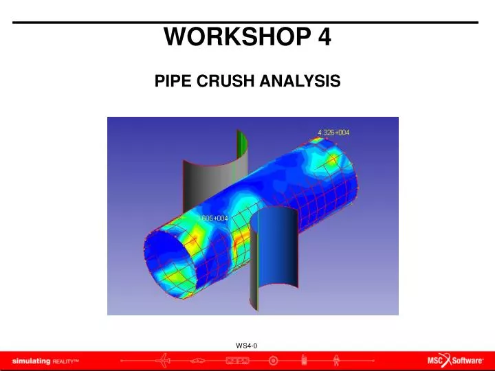
WORKSHOP 4 PIPE CRUSH ANALYSIS
Move 2 in the -Y R=4 Rigid Body 2 Pipe R=3 Rigid Body 1 Move 2 in the Y • Chapter Overview • In this exercise, a model of a cylindrical pipe is modeled as being crushed between rigid bodies. • This model is created using 2D shell elements to model the pipe, and 2D rigid surfaces above and below the pipe.
Objective • Large Deflections/Strains analysis • Elastic-Plastic material model • Rigid – Deformable Contact • Required • A file named crush.bdf in your working directory (Ask your instructor for it if you don’t see it before starting)
Step 1. Open a New Database a b Open a new database , Structures Workspace. • Launch SimXpert. • Select Structures.
a b c d f e Step 2. Set Unit Set the units to English. • Select Tools / Options • Select Units Manager. • Click Standard Units. • Select the line containing English Units (in, lb, s…) • Click OK • Click Apply.
Step 3. Import the crushing.bdf b c a Import the required geometry. • Select File / Import / Nastran • Select crushing.bdf as the File name. • Click Apply.
Step 4. Delete Existing Groups and Contacts Since we want to practice the definitions of contact bodies, we will delete existing related objects firstly • In Model Browser, right click all existing Groups and Conacts, and select Delete command to delete them one by one a
Step 5. Define Plastic Material Modify the material with elastic properties. • In Model Brower, double click Material / MAT1_1_crush.bdf • Change Steel as the Material Name. • Click Advanced icon. • Click Add Constitutive Model / Elasto Plastic b c e d a
Step 5. Define Plastic Material (cont.) Create the material aluminum_1100, with elastic properties. • Select Nonlinear Data Input: Perfectly Plastic. • Enter 36000 in Initial Yield Stress field • Click OK. d e e f f g
a Step 6. LBC:Fix Pipe Select nodes to fix pipe mesh. • On LBC’s tab, select Fixed from the Constraint group • Name : fixed_end • Select nodes at the two ends of the pipe • Click OK. b c d
Step 7. Create contact body - Contact_mid a Create contact body for pipe mesh • On LBC’s tab, select Contact \ Deformable Body (Structural) • Enter Contact_mid as Name • Click Pick Entities field • Choose PSHELL_crush.bdf from Model Browser • Click OK b c d e
Step 8. Create contact body – Contact_top a Create contact body for pipe mesh • On LBC’s tab, select Contact \ Rigid Body (Structural) • Enter Contact_topas Name • Click Pick Entities field • keep only Pick Surfaces optionfrom Pick Filters toolbar • Select the 3 surfaces as the graph below • Select Motion Tab • Switch Motion Control option to Position • Enter Position data as X=0,Y=-2,Z=0 • Click OK d b c f g e h i
Step 9. Check contact normal - Contact_top • Open the Model Browser • Right click Contact \ Contact_top \ PropertiesClick Display • Click Body Tab • Click Display Inward Normals, if it’s necessary, click Reverse Inward Normals. Inward Normal should looks like the one in the following picture. k k l m d
Step 10. Create contact body – Contact_bottom a Create contact body for pipe mesh • On LBC’s tab, select Contact \ Rigid Body (Structural) • Enter Contact_bottom as Name • Click Pick Entities field • keep only Pick Surfaces optionfrom Pick Filters toolbar • Select the 3 surfaces as the graph below • Select Motion Tab • Switch Motion Control option to Position • Enter Position data as X=0,Y=2,Z=0 • Click OK d b c f g h i e
Step 11. Check contact normal-contact_bottom • Open the Model Browser • Right click Contact \ Contact_bottom \ PropertiesClick Display • Click Body Tab • Click Display Inward Normals, if it’s necessary, click Reverse Inward Normals. Inward Normal should looks like the one in the following picture. l k m d
Step 12. Create Contact Table a Create Contact Table • On LBC’s tab, select Contact \ Table • Click OK b
Step 13. Create the Analysis Job Setup and launch the Analysis. • Right-click FileSet and select Create new Nastran Job. • Enter Pipe_Crush as the Job Name. • Solution Type: Implicit Nonlinear Analysis (SOL600). • Click OK a b c d
Step 14. Setup Analysis Parameters Setup the Analysis Parameter • Click right mouse button, Simulation / Pipe_Crush / LoadCases / DefaultLoadCase / Properties • Select SOL600SubcaseNonlinearGeomParameter dialog • Switch Nonlinear Geometric Effects option to Large Displacement/Large Strains • Click Apply • Click Close a b c d e
Step 15. Select Contact Table Select Contact Table. • Right click on Simulations / Pipe_crush / Load Cases / DefaultLoadCase / Select BCTABLE • Click BCTABLE_1 from Model Browser / Contact • Click OK. b a
Step 16. Select Load/BCs Select Load/BCs. • In Model Browser, right click Simulation / Pipe_Crush / Load Cases / DefaultLoadCase / Load/Boundaries / Select Lbc Set • Select DufaultLbcSet • Click OK.. b c a
Step 17. Output Requests-Element Results • Right Click on Output Requests to add the following outputDisplacement (1) & Total Strain Tensor (301) Plastic Strain Tensor (321) Cauchy Stress Tensor (341) a
Step 18. Run this job Run this job • Open Model Browser, click right mouse button at Pipe_Crush,select Run. a
Step 19. Attach Results Attach results files, *.t16 • Select File \ Attach Results\ Result Entities… • Choose pipe_crush.marc.t16 • Click OK b a c
Step 20. Display Results: Deformation Display Deformation • Plot type: Deformation • Result Cases: select the last one • Result Type: Displacement,Translation • Click Update d c a b
Step 21. Display Results: Stress Display Stress • Plot type: Fringe • Result Cases: select the last one • Result type: Result Type: Stress,Cauchy • Derivation: von Mises • Click Update a e d c b