Download
1 / 45
450 likes | 658 Views
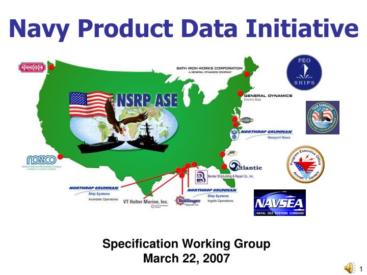
Navy Product Data Initiative. Specification Working Group March 22, 2007. Specification Working Group Introductions. Current Specification Working Group Team General Dynamics Electric Boat - Tim Ahern Northrop Grumman Newport News - Pat Kennedy (Lead)

E N D
Navy Product Data Initiative Specification Working Group March 22, 2007
Specification Working Group Introductions Current Specification Working Group Team • General Dynamics Electric Boat - Tim Ahern • Northrop Grumman Newport News - Pat Kennedy (Lead) • Northrop Grumman Ship Systems - Don Sauvage/Mark Bernasconi • CSC - Keith Back • NSWC Carderock - Ben Kassel
Specification Working Group Agenda • Introductions • Specification Working Group Task/Purpose/Status • Vision • Scope • What is in scope • What is out of scope • Spec Outline • Review Generic Scenario illustrating Need for Configuration Management at the Piece Part Level.
Specification Working Group Task/Purpose/Status Task/Purpose Develop a consensus, specification which defines key performance requirements for those elements of an Integrated Product Data Environment (IPDE) System focusing primarily on the PDM capabilities and interfaces with CAD/CAM/CAE, ERP and catalog systems. Accomplishments • Collected various documents to mine for input • Began Mining of existing documents • Defined scope and outline for specification • Generated initial draft of sample Configuration Management section of specification • Created generic scenario indicating need for configuration management at the piece part level. • Established collaboration site for SWG Next Steps • Continue mining of existing documents (ECD 12/25/07) • Complete Iteration of drafts of sample Configuration Management section of spec (ECD 6/30/07) • Develop/iterate drafts of other sections of specification
Specification Working Group Vision • More capable ships will be delivered at a lower cost, with improved design-build cycle time, and with a significant reduction in the cost of changes. These gains will be achieved because: • Lower cost • Each Navy shipbuilder will maintain spec-compliant IPDE solutions; BUT Yards choose - Navy will NOT dictate an IPDE • Individual IPDE components can be upgraded / replaced without major disruption • Software cost and development risk for incremental IPDE improvements can be spread across multiple programs / yards for shared benefit • Improved design-build cycle time • Information will be readily communicated to other yards, suppliers, Navy, and classification society reviewers. • Enhanced Sharing of Best Practices (e.g., Design Practices) across the Enterprise • Best-of-breed software, including third party software, can be selected / shared • Reduction in the cost of changes • Non-value added labor will be reduced searching for, transforming, and validating ship info
Specification Working Group In Scope Configuration management • Configuration Units (class, flight, hull, system, assembly, Piece Part,…..) • Access Control Change Management • Status Dependency Management Collaboration • Design in context (all disciplines working in same model) • Planning • ILS • Construction • Design reviews and oversight (internal and external) • Interface requirements In service support requirements • As maintained product model/configuration Interoperability • Minimum data elements for various objects • Data Exchange via Standards and Open Architecture
Specification Working Group Out of Scope Ability to handle various DOD security levels Single sign-on Implementation of Workflow Management Defining what portion of the spec is to be met in CAD, PDM, or CAE system, etc… Complete CAD/CAE/ERP/Catalog tool functionality requirements Standard parts catalog These requirements are not waived – just not included in this spec
Specification Working Group Current Spec Outline (1/3) INTRODUCTION Purpose Scope Vision Acknowledgements Executive Summary
Specification Working Group Current Spec Outline (2/3) REQUIREMENTS Open Architecture Qualifications Configuration management Configuration Units Access Control Ability to navigate through the IPDE to the appropriate configuration unit. Reporting Change Management Status Dependency Management Change Notification Collaboration Design in context (all disciplines working in same model) Planning ILS Construction Design reviews and oversight (internal and external) Interface requirements In service support requirements As maintained product model/configuration Interoperability Minimum data elements for various objects Data Exchange via Standards and Open Architecture
Specification Working Group Current Spec Outline (3/3) Appendices A. Glossary B. References C. Sample Piece Part CM Scenario D. Sample As-Maintained Product Model
Configuration Management ScenarioIntroduction • The purpose of this scenario is to illustrate the relative merits of managing the configuration of the product model at the part level as compared to a document level. • The data presented in this example was created simply for the purpose of this demonstration. It is loosely based on the Fuel Oil fill and transfer system of a Torpedo Weapons Retriever (TWR 841) • The TWR 841 drawings and product model data are Approved for Public Release: Distribution Unlimited • The scenario compares the alternative configuration management approaches over 8 years as a pipe run is modified and maintained for a class of 8 ships.
Configuration Management ScenarioSimplification of the Change Process Complexity • Change is limited to a single pipe run - a small portion of a ship product model • Change is limited to BOM and geometric data and not many other data types • As soon a change is made it is implemented on a ship • Does not show collateral change impact on associated objects • Does not show collateral impact on precursor or derived deliverables such as diagrams, drawings or technical documentation • Does not illustrate the representative volume of change
Configuration Management ScenarioDefinitions Part: a catalog part Part Instance: a part that has been located in ship’s position Note: For the purpose of this presentation, the terms part and part instance are used interchangeably. Part-Based Configuration Management: An approach by which the configuration unit is at the part level Document-Based Configuration Management: An approach by which the configuration unit is at a document level (i.e. a collection of parts)
Version G Model P9-1 2 ½ Veg Fiber Gasket P3-1 2 ½ SO Flange FF P4-1 2 ½ Sch 40 pipe (6") P5-1 2 ½ 90 deg BW elbow LR Sch 40 P6-1 2 ½ Sch 40 pipe (39") P5-2 2 ½ 90 deg BW elbow LR Sch 40 P7-1 2 ½ P9-1 2 ½ Veg Fiber Gasket P3-1 2 ½ SO Flange FF P8-1 2 ½ Sch 40 bent pipe (126.75") P3-2 2 ½ SO Flange FF P13-1 Hose bib P14-1 2 ½ Threaded Flange FF P9-1 2 ½ Veg Fiber Gasket P3-1 2 ½ SO Flange FF P4-1 2 ½ Sch 40 pipe (6") P5-1 2 ½ 90 deg BW elbow LR Sch 40 P6-1 2 ½ Sch 40 pipe (39") P5-2 2 ½ 90 deg BW elbow LR Sch 40 P7-1 2 ½ Sch 40 pipe (79") P1-1 2 ½ Hose Gate Valve Flange FF P9-1 2 ½ Gasket P3-1 2 ½ SO Flange FF P3-2 2 ½ SO Flange FF P10-1 2 ½ Sch 40 bent pipe (68.5") P3-3 2 ½ SO Flange FF P9-2 2 ½ Gasket Version J Model Version K BOM Version J BOM Version I BOM Version H BOM Version I Model Version H Model Version K Model Configuration Management ScenarioIntroduction toDocument-Based Approach for Change Management • Multiple parts are configuration managed in single document • Traditional approach for change management in Design/Engineering Systems • Each unique configuration requires a unique document • Changes require duplicating unaffected parts in a copied document • Class and flight changes require repeating effort across multiple documents P1-1 / 2 ½ Hose Gate Valve Flange FF P9-1/2 ½ Veg Fiber Gasket P3-1 / 2 ½ SO Flange FF P8-1 / 2 ½ Sch 40 bent pipe (126.75") P3-2 / 2 ½ SO Flange FF Version G BOM
Query Criteria ? X DATA BASE Class: TWR841 Hull: 1 System: Fuel X-fer Detail #: 10 As-Built: No Current: Yes Date: No USER QUERIESCriteria includes Hull Number(s) OK Cancel P15-1 P13-1, P14-1, P9-5 P9-1, P3-1 P4-1 P5-1 SYSTEM RESPONSE A ‘Dynamic Assembly” P6-1 P5-2 P7-1 Hull 1 Configuration Configuration Management Scenario Introduction to Parts-based Approach for Change Management • Traditional approach for change management in Execution Systems • Authors and configuration manages changes at the part level • Unique configurations are dynamically assembled by part-level effectivity
Query Criteria ? X DATA BASE Class: TWR841 Hull: 5 System: Fuel X-fer Detail #: 10 As-Built: No Current: Yes Date: No USER QUERIESCriteria includes Hull Number(s) OK Cancel P1-1 P9-1, P3-1 P3-2 10-1 11-2 SYSTEM RESPONSE A ‘Dynamic Assembly” P9-4, P3-6 P12-1 P3-5, P9-3 P11-1 Hull 5 Configuration Configuration Management Scenario Introduction to Parts-based Approach for Change Management • Traditional approach for change management in Execution Systems • Authors and configuration manages changes at the part level • Unique configurations are dynamically assembled by part-level effectivity
Configuration Management ScenarioChange Applicability across Eight Hull Class Note: Change descriptions are on following slides Change No. 4 Change No. 5 Change No. 3 8 Hull 8 Built Version G Hull 7 Built Version G 7 Change No. 2 Hull 6 Built Version D Hull 6 Ship Alt Version G 6 Hull Change No. 1 5 Hull 5 Built Version D Hull 5 Ship Alt Version G Hull 5 Ship Alt Version H Hull 4 Built Version B Hull 4 Ship Alt Version G Hull 4 Ship Alt Version D 4 Initial Design Hull 3 Built Version B Hull 3 Ship Alt Version D Hull 3 Ship Alt Version G Hull 3 Ship Alt Version K 3 Hull 2 Ship Alt Version C Hull 2 Built Version A Hull 2 Ship Alt Version F Hull 3 Ship Alt Version J 2 Hull 1 Built Version A Hull 1 Ship Alt Version E Hull 3 Ship Alt Version I 1 1 2 3 4 5 6 7 8 Year
Configuration Version A Hull 1, 2 Configuration Management ScenarioOriginal Configuration Original Configuration (hulls 1,2):
Configuration Management ScenarioChange Number 1 Change No. 1 (affects hulls 3,4): • A piece of equipment was placed on the frame 12 bulkhead for hulls 3 and follow that requires the pipe run to be re-routed. In addition, a new manufacturing process eliminated the need for straight pipes and elbows. • Hull 3 and 4 used bent pipe in lieu of the straight pipe and elbows. Configuration Version A Hull 1 and 2 Configuration Version B Hull 3 and 4 Original New
Configuration Version A Hull 1 and As-Built Hull 2 Configuration Version C Hull 2 Configuration Version B As-Built Hull 3, 4 Configuration Version D Hull 3, 4, 5, 6 Revised New Configuration Management Scenario Change Number 2 Change No. 2: (affects hulls 2,3,4,5,6): • A change was made to an adjacent spool for ships 2 – n. • The change required a flange to be placed on the end of the spool. • Hull 1 was not modified. • Hull 2 required a SHIPALT. • Hull 3 and hull 4 required a SHIPALT. • Hull 5 and hull 6 were built with the flange incorporated into the design. Configuration Version A Hull 1 and 2 Configuration Version B Hull 3 and 4 Old
Configuration Version E Hull 1 Configuration Version A As-Built Hull 1, 2 Configuration Version C Obsolete Configuration Version G Hull 3, 4, 5, 6, 7, 8 Configuration Version D As-Built Hull 5, 6 Configuration Version F Hull 2 Revised New Configuration Management ScenarioChange Number 3 Change No. 3 (affects hulls 1 - n): • Gasket material was changed from cork to vegetable fiber for the entire class • No geometric changes to product model • Hull 1, 2, 3, 4, 5 and 6 required a SHIPALT. • Hull 7 and 8 were built with the vegetable fiber gasket Configuration Version A Hull 1 and As-Built Hull 2 Configuration Version C Hull 2 Configuration Version D Hull 3, 4, 5, 6 Old
Configuration Version G Hull 3, 4, 6, 7, 8 Configuration Version H Hull 5 New Revised Configuration Management ScenarioChange Number 4 Change No. 4 (affects hull 5): • A mission change to hull 5 required the pipe to be rerouted around a newly installed piece of equipment. • In addition a strainer was added. • Hull 5 required a SHIPALT. Configuration Version G Hull 3, 4, 5, 6, 7, 8 Old
Configuration Version K Hull 3 Configuration Version E Hull 1 Configuration Version E Obsolete Configuration Version J Hull2 Configuration Version F Hull 2 Configuration Version F Obsolete Configuration Version G Hull 3, 4, 6, 7, 8 Configuration Version G Hulls 4, 6, 7, 8 Configuration Version I Hull 1 Revised New Old Configuration Management ScenarioChange Number 5 Change No. 5 (affects hulls 1,2,3): • The port side fuel fill valve was showing premature wear on hulls 1, 2, and 3. • The hose gate valve (P1) was no longer available and was replaced by a hose bib (P13), flange (P14), gasket (P9), and gate valve (P15). • This required a change to hull 1 which uses straight pipe, elbows and does not have the flange at the end of the spool, • Hull two which uses straight pipe, elbows, and does have a flange at the end of the spool, and • Hull three which uses bent pipe and has a flange at the end of the spool.
Configuration Management ScenarioOverlay of Document vs. Parts-based Management Document Based Configurations Part Based
Document Based Original Configuration (hulls 1,2): VERSION A Configurations Part Based Document-Based: This approaches require 8 parts to account for the initial design configuration. Part-Based: This approaches also require 8 parts to account for the initial design configuration. Configuration Management ScenarioOriginal Configuration: Document vs. Parts-Based Approach
Configuration Management Scenario Change No. 1: Document vs. Parts-Based Approach Document Based Change No. 1 (affects hulls 3,4): • A piece of equipment was placed on frame 12 bulkhead for hulls 3 and follow requiring the pipe run to be re-routed. In addition, a new manufacturing process eliminated the need for straight pipes and elbows. • Hull 3 and 4 used bent pipe in lieu of the straight pipe and elbows. VERSION A VERSION A VERSION B Hulls 3,4 Configurations Old New Part Based Document-Based Approach: Results in 2 models with 3 duplicated parts and 1 new part. Part-Based Approach: Requires in 1 new part to account for this change.
Configuration Management ScenarioChange No. 2 : Document vs. Parts-Based Approach Document Based Change No. 2: (affects hulls 2,3,4,5,6): • A change was made to an adjacent spool for ships 2 – n. • The change added a flange to the end of the spool • Hull 1 was not modified. • Hull 2 required a SHIPALT. • Hull 3 and hull 4 required a SHIPALT. • Hull 5 and hull 6 were built to the configuration with the flange VERSION A VERSION C Hull 2 Configurations VERSION B VERSION D Hulls 3,4,5,6 VERSION B VERSION D Part Based New Old Document-Based Approach: Results in 2 additional models for a total of 4 models; one reflects as-built configuration for hull 2; The work to accomplish the flange change was required to be performed on each of the copied models; Results 13 additional duplicate parts. Parts-Based Approach: Requires one new part to account for this change.
Configuration Management ScenarioChange No. 3 : Document vs. Parts-Based Approach Change No. 3 (affects hulls 1 - n): • Gasket material was changed from cork to vegetable fiber for the entire class • No geometric changes to product model • Hull 1, 2, 3, 4, 5 and 6 required a SHIPALT. • Hull 7 and 8 were built with the vegetable fiber gasket Document Based VERSION E VERSION A Hull 1 Configurations VERSION F VERSION C Hull 2 VERSION G VERSION D Hulls Part Based 3,4,5, 6,7,8 Document-Based Approach: Results in 3 additional models for a total of 7 models; 4 models reflect historical as-built or as-maintained configurations; The work to accomplish the flange change was required to be performed on all 3 models representing valid configurations; Results in 21 parts duplicated across multiple models. Parts-Based Approach: Requires one new part to account for this change.
Configuration Management Scenario Change No. 4 : Document vs. Parts-Based Approach Change No. 4 (affects hull 5): • A mission change to hull 5 required the pipe to be rerouted around a newly installed piece of equipment. • In addition a strainer was added. • Hull 5 required a SHIPALT. Document Based VERSION H VERSION G Hull 5 Configurations Old New Part Based Document-Based Approach: Results in 1 additional model; Results in 4 more parts being duplicated in the copied model. Parts-Based Approach: This change requires 11 new parts applicable for hull 5.
Configuration Management Scenario Change No. 4 : Document vs. Parts-Based Approach Change No. 5 (affects hulls 1,2,3): • The port side fuel fill valve was showing premature wear on hulls 1, 2, and 3. • The hose gate valve (P1) was no longer available and was replaced by a hose bib (P13), flange (P14), gasket (P9), and gate valve (P15). • This required a change to hull 1 which uses straight pipe, elbows and does not have the flange at the end of the spool, • Hull two which uses straight pipe, elbows, and does have a flange at the end of the spool, and • Hull three uses bent pipe and has a flange at the end of the spool. Document Based Configurations VERSION E VERSION I Hull 1 VERSION F VERSION J Hulls 2 VERSION G VERSION K Hulls 3 Part Based Document-Based Approach: Results in 3 additional models; The change to add the four parts needs to be accomplished in each of the copied model requiring the change to be accomplished 3 times; results in a total of 27 additional duplicated parts. Parts-Based Approach: This change results in 4 new parts applicable to hulls 1,2, and 3.
HOSE GATE VALVE GATE VALVE GASKET THREADED FLANGE HOSE BIB Configuration Management ScenarioDemonstration: Document vs. Parts-Based Approach Configuration management at the parts level and the document level will be illustrated for Change #5. To review, the hose gate valve is to be replaced. However, since that specialty item is no longer available, four separate parts are required to support this engineering change.
Configuration Management ScenarioDemonstration: Document-based Approach (Hulls 1-3) ENGINEERING CHANGE Change can be initiated via a formal Engineering Change Request or an informal process… ….In the Document-Based approach, this effectivity will be applied at the document level after the document (s) have been updated.
Configuration Management ScenarioDemonstration: Document-based Approach (Hull 1) AUTHOR CHANGESRemove the Hose Gate Valve And replace it with a gate valve, gasket, flange, and hose bib. Open the file containing the model of the pipe run for hull number 1. This is version E Add Gate Valve Add Gasket Add Hose Bib SAVE CHANGES A new document (file) will be save as version I. Remove Hose Gate Valve Add Threaded Flange UPDATE EFFECTIVITY Update the document effectivity table to reflect the new file being applicable to hull 1.
Configuration Management ScenarioDemonstration: Document-based Approach (Hull 2) Open the file containing the model of the pipe run for hull number 2. This is version F AUTHOR CHANGESRemove the Hose Gate Valve And replace it with a gate valve, gasket, flange, and hose bib. Add Gate Valve Add Gasket Add Hose Bib SAVE CHANGES A new document (file) will be save as version J. Remove Hose Gate Valve UPDATE EFFECTIVITY Update the document effectivity table to reflect the new file being applicable to hull 2. Add Threaded Flange
Configuration Management ScenarioDemonstration: Document-based Approach (Hull 3) Open the file containing the model of the pipe run for hull number 3. This is version G AUTHOR CHANGESRemove the Hose Gate Valve And replace it with a gate valve, gasket, flange, and hose bib. Add Gate Valve Add Gasket Add Hose Bib SAVE CHANGES This will be saved as version K. Remove Hose Gate Valve Add Threaded Flange UPDATE EFFECTIVITY Update the document effectivity table to reflect the new file being applicable to hull 3.
Configuration Management ScenarioDemonstration: Parts-based Approach (Hulls 1-3) ENGINEERING CHANGE In the Parts-based approach, the same Change Request can initiate a change… …but the targeted effectivity will be used to eliminate complexity and user burden to understand the mechanisms to managing effectivity
WORK CONTEXT Defined by Engineering Work or Change Order Work Context ? X Class: TWR841 Hull: 1,2,3 System: Fuel X-fer Detail #: 10 As-Built: N Current: Yes Date: No USER QUERY Defined by Work Context DATABASE Filtered Parts List ? X OK Cancel SYSTEM RESPONSE Filtered Parts List for Hulls 1,2 and 3 OK Cancel Refresh Configuration Management ScenarioDemonstration: Parts-based Approach (Hulls 1-3)
Filtered Parts List ? X OK Cancel Refresh Configuration Management ScenarioDemonstration: Parts-based Approach (Hulls 1-3) BUILD ASSOCIATED 3D VIEW Based on the parts-based hull effectivity, the system dynamically assembles the current configurations for: hull #1 , hull #2 , and hull #3
Work Context ? X Class: TWR841 Hull: 1,2,3 System: Fuel X-fer Detail #: 10 As-Built: N Current: Yes Date: No OK Cancel Configuration Management ScenarioDemonstration: Parts-based Approach (Hulls 1-3) AUTHOR CAD CHANGES 1. Remove Hose Gate Valve 2. Place Gate Valve 3. Place Gasket 4. Place Threaded Flange 5. Place Hose Bib CAD Operator performs change using normal CAD modeling techniques
Work Context ? X Class: TWR841 Hull: 1,2,3 System: Fuel X-fer Detail #: 10 As-Built: N Current: Yes Date: No SAVE CHANGES User completes work and performs a standard Save SYSTEM AUTOMATION System adds only new parts and applies part-level effectivity for based upon Work Context Filtered Parts List ? X AUTHOR CHANGES CAD Operator Performs Change One Time OK Cancel Filtered Parts List ? X OK Cancel Refresh OK Cancel Refresh Configuration Management ScenarioDemonstration: Parts-based Approach (Hulls 1-3)
DATABASE Filtered Parts List ? X OK Cancel Refresh Configuration Management ScenarioDemonstration: Parts-based Approach (Hulls 1-3) DATABASE These changes are synchronously added to the configuration management database
Configuration Management ScenarioComplexity Recap • The Configuration Management Scenario in this presentation represents a dramatic simplification in scope and the complexity • Limited to a single pipe run • Limited to BOM and geometric data • Does not consider collateral impact on associated and surrounding objects • Does not account for updating derivative docs • Does not illustrate the representative volume of change Despite these simplifications the scenario illustrates the core complexity and inherent inefficiency of a document based approach for managing change
Configuration Management ScenarioSummary Document-based Change Management Issues • This basic change scenario illustrates the negative impacts associated with the ever-increasing data duplication across multiple documents with document-based product configuration management • The part count rapidly increases to 4x the actual number of parts with only 8 ships • The labor required to affect change increases rapidly over time • n documents are created for n product configurations – requires every class change to be accomplished n times • Checking, review and approval of each change will need to be performed n times • Managing the correct configuration of data to represent a ship zone or area • Part proliferation within documents results in a cascading complexity to manage related product data • System interfaces • Drawing sheets and tech pubs • Bill of Materials • The complexity to manage single system changes is compounded by hundreds of systems in an area/zone and over a thousand systems for an entire ship • High cost of change has resulted in the product models not being maintained for the lifecycle • These issues inhibit making product changes for follow-on design, manufacturing or maintenance improvements • Attribute changes • Pipe spool sketches • Work Packages, etc…
Configuration Management ScenarioSummary Parts-based Change Management Benefits • The parts-based product configuration management eliminates data duplication by managing change at the part level • Elimination of data duplication reduces redundant, non-value added effort to affect change. • Parts-based management allows for dynamic assembly of part views • Hull specific applicability • Integrated design Parts-based Change Management Challenges • NPDI team is not aware of any CAx vendor or product that currently supports parts-based product configuration management. • The authoring tools (CAx and PDM/PLM tools) will need to open their data models to allow for cross vendor parts-based product configuration management. • System design review • Work package graphics
Configuration Management ScenarioConclusion • The team is in agreement that there is a strong need to develop a parts-based approach to solve the complexity associated with document-based change management • Based on this agreement the team has included the parts-based approach in the draft NPDI specification