Download
1 / 31
440 likes | 1.24k Views
CHAPTER 7 Digital Filter Design. Wang Weilian wlwang@ynu.edu.cn School of Information Science and Technology Yunnan University. Outline. About Digital Filter Design Bilinear Transformation Method of IIR Filter Design Design of Lowpass IIR Digital Filters

E N D
CHAPTER 7Digital Filter Design Wang Weilian wlwang@ynu.edu.cn School of Information Science and Technology Yunnan University
Outline • About Digital Filter Design • Bilinear Transformation Method of IIR Filter Design • Design of Lowpass IIR Digital Filters • Design of Hignpass, Bandpass, and Bandstop IIR Digital Filter • FIR Filter Design Based on Windowed Fourier Series • Computer-Aided Design of Digital Filters • Digital Filter Design Using MATLAB
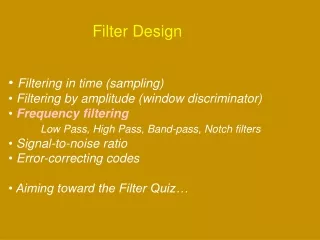
About Digital Filter Design • The most important step in the development of a digital filter :Determine a realizable transfer function G(z) • Digital Filter Specifications (1) magnitude response specifications in the passband and the stopband are given with some acceptable tolerances (2) A transition band is specified between the passband and the stopband to permit the magnitude to drop off smoothly
About Digital Filter Design • Passband edge frequency • Stopband edge frequency • Peak ripple value of passband • Peak ripple value of stopband • Peak passband ripple • Minimum stopband attenuation • Sample frequency FT
N å - = n H ( z ) h [ n ] z = n 0 About Digital Filter Design • Selection of the Filter Type (1)The objective of digital filter design is to develop a causal transfer function H(z) meeting the frequncy specifications. (2)FIR and IIR Digital Filter FIR Digital Filter IIR Digital Filter
± About Digital Filter Design
About Digital Filter Design The order NFIR of an FIR filter is higher than the order NIIR of an equivalent IIR filter meeting the same magnitude specifications The ratio NFIR/ NIIRis typically of the order of 10 or more (the IIR filter usually is computationally more efficient)
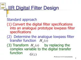
About Digital Filter Design • Basic Approaches to Digital Filter Design Step1:convert the digital filter specifications into analog lowpass prototype filter specifications Step2:determine the analog lowpass filter transfer function Ha(s) Step3:transform Ha(s) into the desired digital filter transfer function G(z)
About Digital Filter Design • Why analog? (1)Analog approximation techniques are highly advanced (2)They usually yield closed-form solutions (3)Extensive tables are available for analog filter design (4)Many applications require the digital simulation of analog filters
W About Digital Filter Design • How to convert an analog prototype transfer function Ha(s) into a digital IIR transfer function G(z)? (1)the imaginary(j ) axisin the s-plane be mapped onto the unit circle of the z-plane (2)A stable analog transfer functon be transformed into a stable digital transfer function
About Digital Filter Design • Estimation of the Filter Order IIR: The order of G(z) is determined from the transformation being used to convert Ha(s) into G(z)(The determination of Ha(s) is refered to Eq.(5.33),(5.41),or(5.51) FIR(lowpass digital filter): For narrowband filter For wideband filter
Bilinear Transformation Method of IIR Filter Design • Bilinear transformation is more commonly used to design IIR digital filters based on the conversion of analog prototype filters • The Bilinear Transformation S-plane to z-plane G(z)= Ha(s) | The transformation is a one-to-one mapping. It maps a single point in the s-plane to a unique point in the z-plane
Bilinear Transformation Method of IIR Filter Design • Digital filter design procedure: Step1 the invert bilinear transformation is applied to the digital filter specifications to arrive at the specifications of the analog filter function Step2 the bilinear transformation is employed to obtain the desired digital transfer function G(z) from the analog transfer function Ha(s) desired to meet the analog filter specifications
Bilinear Transformation Method of IIR Filter Design • When T=2(T has no effect on the G(z)) If then <1 If >0 then >1
Bilinear Transformation Method of IIR Filter Design • When and
Bilinear Transformation Method of IIR Filter Design • Design of Digital IIR Notch Filters Example a second-order IIR notch filter Analog transfer function: Applying a bilinear transformation : Rewrite it: Notch frequency Notch bandwidth
Design of Lowpass IIR Digital Filters • Steps of designing a lowpass IIR digital filter Step1: get the digital filter specifications( ) Step2: convert to analog filter specifications with bilineat transformation Step3: design analog transfer function Ha(s) Step4: transfer Ha(s) to H(z) since
Design of Lowpass IIR Digital Filters • Example Passband edge frequency is 0.25 with a passband ripple of 0.5dB Stopband edge frequency is 0.55 with a stopband attenuation of 15dB Then
Design of Lowpass IIR Digital Filters • From the passband ripple of 0.5dB obtaining From the stopband attenuation of 15dB obtaining Then since then we get
Design of Lowpass IIR Digital Filters The transfer function of third-order lowpass Butterworth is Then we can get
Design of Highpass, Bandpass, and Bandstop IIR Digital Filters • To design IIR filters there are two approches can be followed • First approch: Step1: prewarp the digital frequency specifications to arrive at the specifications of an analog filter of the same type.
Design of Highpass, Bandpass, and Bandstop IIR Digital Filters • Step2: convert the frequency specifications of HD(s) into that of a prototype analog lowpass filter HLP(S) ( s is the Laplace transform variable of the prototype analog lowpass filter HLP(S) and is the Laplace transform variable of the desired analog filter )
Design of Highpass, Bandpass, and Bandstop IIR Digital Filters • Step3: Design the analog lowpass filter HLP(S) using the method described in Section 5.4 • Step4: convert the transfer function HLP(S) into HD(S) using the inverse of the frequency transformation used in step2 • Transform the transfer function HD(S) using the bilinear transformation to arrive at the desired digital IIR transfer function GD (Z)
Design of Highpass, Bandpass, and Bandstop IIR Digital Filters • The second approach: Step1: prewarp the digital frequency specifications to arrive at the specifications of an analog filter of the same type.
Design of Highpass, Bandpass, and Bandstop IIR Digital Filters • Step2: convert the frequency specifications of HD(s) into that of a prototype analog lowpass filter HLP(S) ( s is the Laplace transform variable of the prototype analog lowpass filter HLP(S) and is the Laplace transform variable of the desired analog filter )
Design of Highpass, Bandpass, and Bandstop IIR Digital Filters • Step3: Design the analog lowpass filter HLP(S) using the method described in Section 5.4 • Step4: convert the transfer function HLP(S) into the transfer function GLP(Z) of an IIR digital filter using the bilinear transformation • Step5: transform GLP(Z) into the desired digital transfer function GD(z) using the appropriate spectral transformation discussed in Section 7.5
Design of Highpass, Bandpass, and Bandstop IIR Digital Filters • The functions we usually used in Matlab lp2hp: transform the lowpass analog filter to highpass analog filter lp2bp: transform the lowpass analog filter to bandpass analog filter lp2bs : transform the lowpass analog filter to bandstop analog filter