Download
1 / 63
750 likes | 1.72k Views
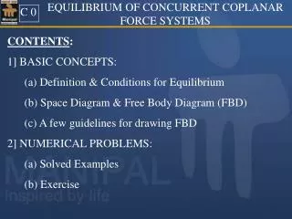
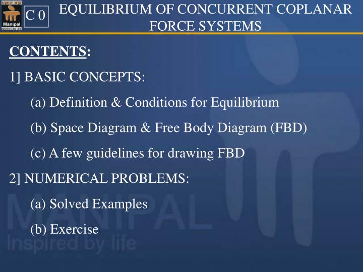
EQUILIBRIUM OF CONCURRENT COPLANAR FORCE SYSTEMS. C 0. CONTENTS : 1] BASIC CONCEPTS: (a) Definition & Conditions for Equilibrium (b) Space Diagram & Free Body Diagram (FBD) (c) A few guidelines for drawing FBD 2] NUMERICAL PROBLEMS: (a) Solved Examples

E N D
EQUILIBRIUM OF CONCURRENT COPLANAR FORCE SYSTEMS C 0 CONTENTS: 1] BASIC CONCEPTS: (a) Definition & Conditions for Equilibrium (b) Space Diagram & Free Body Diagram (FBD) (c) A few guidelines for drawing FBD 2] NUMERICAL PROBLEMS: (a) Solved Examples (b) Exercise
EQUILIBRIUM OF CONCURRENT COPLANAR FORCE SYSTEMS T1 Definition:- If a system of forces acting on a body, keeps the body in a state of rest or in a state of uniform motion along a straightline, then the system of forces is said to be in equilibrium. ALTERNATIVELY, if the resultant of the force system is zero, then, the force system is said to be in equilibrium.
Conditions for Equilibrium of Concurrent Coplanar Force System Y X T2 A coplanar concurrent force system will be in equilibrium if it satisfies the following two conditions: i) Fx = 0; and ii) Fy = 0 i.e. Algebraic sum of components of all the forces of the system, along two mutually perpendicular directions, is ZERO.
F3 F2 F2 Fig 1.(a) F1 F3 F1 F4 F3 F3 F2 F5 F2 Fig 1.(b) F1 F4 F1 F5 T3 Graphical conditions for Equilibrium Triangle Law: If three forces are in equilibrium, then, they form a closed triangle when represented in a Tip to Tail arrangement, as shown in Fig 1.(a). Polygonal Law: If more than three forces are in equilibrium, then, they form a closed polygon when represented in a Tip to Tail arrangement, as shown in Fig 1.(b).
F1 Fig (2) T4 LAMI’S THEOREM If a system of Three forces is in equilibrium, then, each force of the system is proportional to sine of the angle between the other two forces (and constant of proportionality is the same for all the forces). Thus, with reference to Fig(2), we have, F3 α F2 γ Note: While using Lami’s theorem, all the three forces should be either directed away or all directed towards the point of concurrence.
Cable P = 2kN 3 m Sphere θ 30 R=1m. wall T5 SPACE DIAGRAMS & FREE BODY DIAGRAMS Space Diagram(SPD):The sketch showing the physical conditions of the problem, like, the nature of supports provided; size, shape and location of various bodies; forces applied on the bodies, etc., is known as space diagram. Eg. Fig 3(a) is a space diagram Fig 3 (a) SPD Weight of sphere = 0.5 kN
Cable P = 2kN 3 m Sphere θ 30 R=1m. wall Fig 3 (a) SPD Weight of sphere = 0.5 kN T6 Free Body Diagram(FBD) :It is an isolated diagram of the body being analyzed (called free body), in which, the body is shown freed from all its supports and contacting bodies/surfaces. Instead of the supports and contacting bodies/surfaces, the reactive forces exerted by them on the free body is shown, along with all other applied forces. Eg. Fig 3(b) is a Free Body Diagram of Fig 3(a).
W=0.5kN T Cable P = 2kN P=2kN 3 m Sphere θ 30 θ 30 Rw R=1m. wall T = Tension in the cable Rw = Reaction of the wall Weight of sphere=0.5kN Fig 3(b) FBD Fig 3(a) SPD T6 Note: Free Body Diagrams should be NEAT, LEGIBLE & SUFFICIENTLY BIG. Only the details required for the analysis of the problem are to be shown.
T7 A Few Guidelines for Drawing FBD 1) Tensile Force: It is a force trying to pull or extend the body. It is represented by a vector directed away from the body. 2) Compressive Force: It is force trying to push or contract the body. It is represented by a vector directed towards the body. 3) Reactions at smooth surfaces: The reactions of smooth surfaces, like walls, floors, Inclined planes, etc. will be normal to the surface and pointing towards the body. 4) Forces in Link rods/connecting rods: These forces will be acting along the axis of the rod, either towards or away from the body. (They are either compressive or tensile in nature).
P =40N 40N T8 5) Forces in Cables (Strings or Chords): These can only be tensile forces. Thus, these forces will be along the cable and directed away from the body. 6) Tension in cables on either side of a smooth pulley will be equal in magnitude. (Eg. As shown in Fig)
15 Fig (1) NUMERICAL EXAMPLES P (1) (1) A sphere of 100N weight is tied to a wall by a string as shown in fig (1). Find the tension in the string and the reaction of the wall.
15 T 105 R 165 90 W Fig (1a) FBD P (2) Using Lami’s theorem,
B 30 D A 60 C 40 kN Fig (2) SPD P (3) (2) Determine the magnitude and nature of the forces in the bars AB and AC shown in Fig (2). Neglect size and weight of the pulley.
Y (+ve) FAB X (+ve) Ty 30 60 T =40 kN 30 Tx 60 FAC X Wx Wy W=40 kN Fig (2a) F B D at A (P4) Angle between FAB and FAC = 90º Taking FAC as X-axis and FAB as Y– axis
Y (+ve) FAB X (+ve) Ty 30 60 T =40 kN 30 Tx 60 FAC X Wx Wy W=40 kN Fig (2a) F B D at A (P5) FAC is –ve , FAC is towards ‘A’, So it is Compressive. = +14.64kN FAB is +ve. FAB is towards ‘A’, So it is Tensile.
P 60 A 15 B 60 45 Fig (3) P (6) (3) Two cylinders A & B of weight 400N and 200N respectively, rest on smooth planes as shown in Fig(3). Find the force ‘P’ required for equilibrium.
400N 200N P 60 A 15 RA B 60 RB 60 45 45 Fig (3) P (7) The forces in the system are as shown.
WA=400N Y 120 WB=200N 105 P FBA 15 60 60 15 FAB X RA 135 45 RB Fig (3a) FBD OF ‘A’ Fig (3b) FBD OF ‘B’ P(8) FBD
WA=400N 120 105 15 60 FAB RA 135 Fig (3a) FBD OF ‘A’ P(9) Considering FBD of ‘A’ and Using Lami’s theorem,
P (10) Considering FBD of ‘B’, We have, -------Eqn(1) -----------------Eqn(2) Adding Eqn(1) and Eqn(2), We get,
120mm Q P 40 Fig (4) SPD P (11) (4) Two cylinders P and Q of diameters 100mm and 50mm, weighing 200N and 50N respectively, are placed in a trench as shown in Fig (4). Assuming smooth surfaces determine reactions at all contact points.
From Fig(4), in PQO PQ = 50 + 25 = 75mm PO = 120 – 50 – 25 PO = 45mm. 120mm Q C RC A α RA o P B 40 RB 50 50 Fig (4) SPD P (12) Cos α = 45/75 ; α =53.130
Y WQ = 50N WP = 200N 90 FQP 143.13 C RC α X RA A α FPQ 50 126.87 RB Fig (4a) FBD of ‘P’ Fig (4b) FBD of ‘Q’ P (13) FBD α =53.130
Y WP = 200N FQP α X RA A 50 RB Fig (4a) FBD of ‘P’ P (14) Considering FBD of ‘Q’ and Using Lami’s theorem,
WQ = 50N 90 143.13 C RC α FPQ 126.87 Fig (4b) FBD of ‘Q’ P (15) Considering FBD of ‘P’, We have,
C A B 800mm Fig (5) SPD P (16) (5) Three cylinders A , B and C of diameters 500mm each are arranged as shown in Fig (5). The weights of A and B are 500N each and weight of C is 600N. Determine reactions at all contact points and tension in the string holding A and B.
C α α A o B Q P 800mm Fig (5a) SPD P (17) From Fig(5a), AC = 250 + 250 = 500mm AO = 800/2 = 400mm Cos α = 400/500 ; α =36.87 0
WC= 600N 126.87 126.87 α α RAC RBC RCA 106.26 RCB WA= 500N WB= 500N Fig (5c) FBD of ‘C’ C T T α α RQ RP Fig (5b) FBD of ‘B’ Fig (5a) FBD of ‘A’ P (18) FBD
WC= 600N 126.87 126.87 α α RAC RBC 106.26 Fig (5c) FBD of ‘C’ P (19) Considering FBD of ‘C’ and Using Lami’s theorem,
RCA WA= 500N T α RP Fig (5a) FBD of ‘A’ P (20) Considering FBD of ‘A’, we have, By Symmetry, RP = RQ = 800 N (Or, Using FBD of ‘B’, RQ = 800 N)
B A 30 Fig (6) P (21) (6) Two Spheres, each of radius 1m and mass 1000 kg, rest on smooth surfaces as shown in Fig (6) . Determine reactions at all contact points.
B A R P Q Fig (6) 30 P (22) Weight of Spheres = Mass x g =1000 x 9.81 = 9810 N = 9.81 kN Reaction between A & B will be parallel to Plane QR, as radius is the same.
+ve WB =9.81 kN Y +ve +ve X Y 30 WA =9.81 kN +ve X FBA FAB 30 30 30 RR RP 30 Fig (6b) FBD of ‘B’ RQ Fig (6a) FBD of ‘A’ P (23) FBD
+ve WB =9.81 kN Y +ve X + 30 FAB 30 30 RR + Fig (6b) FBD of ‘B’ P (24) Considering FBD of ‘B’, We have,
+ve + Y WA =9.81 kN +ve X FBA 30 RP + 30 RQ Fig (6a) FBD of ‘A’ P (25) Considering FBD of ‘A’, we have,
B A 30 Fig(7) P (26) (7) Two Spheres A & B, weighing 300N & 600N and having diameters 800mm &1200mm, respectively, rest on smooth surfaces as shown in Fig (7) . Determine reactions at all contact points.
600 200 θ 400 C A B P R Q 30 Fig(7) P (27) AC parallel to plane; AB radial line. Sin θ = BC/AB Sin θ = 200/1000 =11.53 0 Force between A & B will be at an angle of 11.53º to axis parallel to Plane QR. ( Radii are NOT the same in this case.)
+ve WB =300 N Y +ve +ve X Y 30 WA =600 N +ve X FAB θ 30 30 30 FBA RR RP θ 30 Fig (7b) FBD of ‘B’ RQ Fig (7a) FBD of ‘A’ P (28) FBD
+ve WB =300 N Y +ve X + 30 FAB θ 30 30 RR + Fig (7b) FBD of ‘B’ P (29) Considering FBD of ‘B’, We have,
+ +ve Y WA =600 N +ve X 30 FBA RP θ + 30 RQ Fig (7a) FBD of ‘A’ P (30) Considering FBD of ‘A’, We have,
P C Kerb A !50 B Fig (8). P (31) (8) A roller of radius 300mm, weighing 5kN is to be pulled over a kerb of height 150mm, by applying a horizontal force ‘P’ applied at the circumference by means of a rope wrapped around it, as shown in Fig (8). Find (i) The magnitude of force P when it is horizontal ; (ii) The direction and magnitude of the least force P required to pull the roller over the kerb.
P C Kerb W A !50 B RA P (32) NOTE: When the roller is about to roll over the kerb, it loses contact at B. So, there will be no reaction at B. There will be a reaction at A ,(say, RA), only. Therefore at the instant of rolling over the kerb, there will be only 3 forces in equilibrium, viz., Weight (W), P & RA. Since, there are only 3 forces in equilibrium, they will be Concurrent. Thus reaction at A passes through ‘C’, point of concurrence of W & P.
P C 450 O Kerb 150 θ 300 D A 150 !50 B Fig (8) P (33) In Fig (8), From Triangle ADO, From Triangle ACD,
RA 120 P 150 θ C 90 W=5KN θ A B Fig (8A) FBD P (34) CASE (i) Force ‘P’ is Horizontal In Fig (8A), FBD, using Lami’s Theorem,
RA Pmin 120-α θ C α 150 90+α θ W=5KN A B Fig (8B) FBD Case ii P (35) CASE (ii) Force ‘P’ is Least. (at angle ‘α’ w r t Hz.) In Fig (8B), FBD, using Lami’s Theorem, For P to be min., Sin(120- α)=1, or, α = 30 Thus, NOTE: For min. value P is at right angles to RA.
A 30 D B θ C 50 20 kN 30 kN Fig (9) SPD P (36) (9) Determine, the tension in the strings AB, BC, CD and inclination of the segment CD to the vertical, in the system shown in Fig (9).
Y TBA +VE TCD TCB 30 160 50 θ 150 +VE X 50 TBC 20 kN 30 kN Fig 9 (a) FBD of Joint ‘B’ Fig 9 (b) FBD of Joint ‘C’ P (37) FBD
TBA 30 160 150 50 TBC 20 kN Fig 9 (a) FBD of Joint ‘B’ P (38) Considering FBD of Joint ‘B’ and Using Lami’s theorem,
Y +VE TCD TCB 50 θ +VE X 30 kN Fig 9 (b) FBD of Joint ‘C’ P (39) Considering FBD of Joint ‘C’, We have, Dividing Eqn(1) by (2), we get, (NOTE: For this FBD, if we use Lami’s Theorem,we have to expand Sin(50+θ) and solve for θ, which can take more time.)
A 30 D B 60 C θ 20kN 25 kN Fig (10) SPD P (40) (10) A wire is fixed at two points A and D as shown in Fig (10). Determine inclination of the segment BC to the vertical and the tension in all the segments.


![C [0]](https://cdn1.slideserve.com/3218926/slide1-dt.jpg)