Download
1 / 52
530 likes | 748 Views
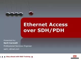
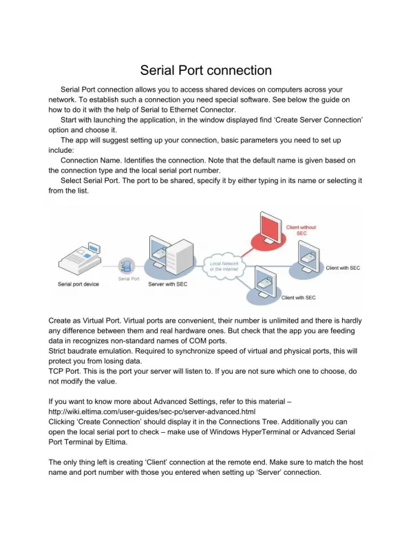
Ethernet and Legacy Access over DSL. Variety of Ethernet Access Solutions – Implementation Scenario. Ethernet over SDH/SONET. Branch. Ethernet over PDH. Branch. RICi-622GE. RICi-622GE. RICi-E1. STM-4/OC-12. GbE. 10BT. GbE. GFP.

E N D
Variety of Ethernet Access Solutions – Implementation Scenario Ethernet over SDH/SONET Branch Ethernet over PDH Branch RICi-622GE RICi-622GE RICi-E1 STM-4/OC-12 GbE 10BT GbE GFP • Extending the reach of the provider’s network over a variety of access technologies • Consistent Ethernet service across different access technologies Branch Branch RICi-155GE RICi-155GE RICi-4/8E1 MLPPP GbE STM-1/OC-3 GbE 10BT EoPDH ADM Branch RICi-16 Branch Ethernet over DSL 100BT SDH IPDSLAM GFP-VCAT LA-210 F.ETH STM-1/OC-3 EFM Bonding GbE GbE Branch IPDSLAM GbE LA-110 Egate Service Provider Packet Switched Network F.ETH Ethernet over Fiber ATM ASMi-54 ASMi-54 ETX-202 F.ETH GbE SHDSL.bis Headquarters ETX-202A GbE Metro Ethernet GbE GbE Branch
Agenda • Agenda: • ASMi-54 • Concept + Applications • LA-110 • Concept + Applications • LA-210 • Concept + OAM • Summary • Appendix • Road Maps • LA Product Family Line • LA-210 Flow Concept • OAM – CC/LB/LT
What is the Business Case? Strong growth of DSL subscribers ~200 million in 2007 expected to grow to 364 million in 2011* What are they used for? • Internet hi-speed access (residential customers) • Added value (residential market - video, gaming, etc.) • Voice over IP services • IP VPN services for business customers * Source: Infonetics Research, Broadband Aggregation Hardware and Subscribers Market Share and Forecasts 4Q07 We have the technology and the infrastructure which provide higher Bandwidth…. …what else can we do with it? • Carrier & Utilities Market (Railways, Highways, CCTV) • Leased line services (E1/T1, n x 64 kbps), FR • Ethernet services for Business customers • Cellular backhaul for 2G/2.5G and 3G networks
ETH & Legacy Over DSL Customer Premises Customer Premises PBX PBX IPDSLAM IPDSLAM E1 PSN Eth/IP/MPLS E1 LA-110 LA-110 SHDSL SHDSL ETH ETH GbE TDMoIP Gateway IPmux Gmux Fast Ethernet TDM CO/POP ASMi-54 ASMi-54 n x SHDSL Fast Ethernet Fast Ethernet Node-B RNC PSN Eth/IP/MPLS GbE LA-210 n x SHDSL GbE Node-B IPDSLAM
SHDSL Products Profile Central Solution MP-2100, MP-4100, DXC-30, LRS-24 MP-4100*, LRS-102 * ASMi-54C – beta Q3/08
ASMi-54 – G.SHDSL.bis Technology Services Link Options ASMi-54 • New SHDSL standard – TC-PAM 32 • Enables 5.7Mbps over 2w • Even higher rate over 8w with bonding ASMi-52 • Standard SHDSL – TC-PAM 16 • Enables 2.3Mbps over 2w • No bonding ETH 2w 5.7 Mbps ASMi-54 ETH 4w 11.4 Mbps ETH ETH 8w 22.8 Mbps
ASMi-54 – Phase 1 Management options • Terminal, Telnet, ConfiguRAD, Out-of-band/In-band Ethernet port • In-band dedicated VLAN to encapsulate management traffic WAN Protocol • EFM bonding - enables each link to synch at different rate. Failure or addition of a link doesn't drop the whole group VLAN Mode • Stacking/stripping based on 802.1D MAC ,802.1Q VLAN • Quality of service (QOS)on the DSL egress direction Fault Propagation • From SHDSL to user interface Estimated Distance • Estimated distance @ 5,696 kbit/s – 2.9 km - with noise-free @26AWG cable • Up to 22.8Mbps over 8 wires Ordering Options • Plastic/Metal box/Rail Mount case • Extended temperature option (-20˚C to +70˚C) New !
ASMi-54 – Phase 2.0 • 4 ETH ports with additional E1/T1 ports • RADview support (RV-EMS-SW/TDM/PC 1.8) • SHDSL.bis repeaters support: • 2W, plastic – S-RPT • 2W, metal IP-67 Outdoor – S-RPT/IP-67 • 4W, metal IP-67 Outdoor – S-RPT-4W 2w 5.7 Mbps ASMi-54 E1/T1 Phase 2.0 4w 11.4 Mbps Available !! Four ETH 8w 22.8 Mbps Beta Q2/08
Central Solution:LRS-102/ASMi-54 Card LRS-102 • 4U, 12 I/O • System redundancy • Central management • Improved pricing • 12 x 16W per ASMi-54 card • High port density - 24 OP-108/106 modules • Under customers validation ASMi-54 Card • Stackable into LRS-102 and MP- 4100 • Supports up to 16 wires on the DSL line • Interfaces: • 8 E1 lines via DB-44 cable balanced • 2 ETH 10/100 Base T ports 2 x power supplies 2 x Common Logic 12 I/O slots
ASMi-54 Point to Point Applications CCTV ASMi-54 ASMi-54 5.7 Mbps ETH Winning Combination / Business Environment: • Built-in Ethernet bridge • High ETH performances • 5.7 Mbps over 2-wire lines – estimated 2.9 km on 26AWG Pumping Station 5.7 Mbps ETH Control Room ASMi-54 ASMi-54 SHDSL.bis Repeater E1/T1 E1/T1 ASMi-54 ASMi-54 Phase 2.0 Phase 2.0 Phase 1.0 Phase 1.0 Four ETH Four ETH
Ethernet and E1 Range Extension over Copper using a Central Solution Key Benefits • Powerful central site solution • Low cost and simplicity • High reliability (PS and main link protection) n x E1/T1 SDH/SONET CP POP PBX E1 LRS-102/MP-4100 ASMi-54 SHDSL.bis ETH n x FETH IP/MPLS Beta Q3/08
ETH & Legacy over DSL Customer Premises Customer Premises PBX PBX IPDSLAM IPDSLAM E1 PSN Eth/IP/MPLS E1 LA-110 Fast Ethernet Fast Ethernet LA-110 SHDSL SHDSL ETH ETH GbE TDMoIP Gateway IPmux Gmux Fast Ethernet TDM CO/POP ASMi-54 ASMi-54 n x SHDSL Node-B RNC PSN Eth/IP/MPLS GbE LA-210 n x SHDSL GbE Node-B IPDSLAM
Evolution of Ethernet and Legacy Service Delivery over DSL Traditional DSLAM ATM • All the way ATM; Ethernet, E1, serial or FR services based on ATM LA-110 Legacy Core ATM ATM ATM Traditional DSLAM with Ethernet Uplink • Ethernet and legacy services over PSN using PWE • IAD to DSLAM segment based on ATM LA-110 PSN Core Ethernet, IP, MPLS ATM Ethernet
LA-110 Interfaces & WAN Protocols 10/100BaseT interface Bridge Router E1/T1 ports (ATM or TDM) Serial data interface (V.35, X.21) SHDSL • 1,2 pairs or 4 pairs (IMA) • Line coding:PAM16 • Data rates up to 2.3 Mbps (2W) • Data rates up to 4.6 Mbps (4W) • Date rates up to 9.2 Mbps (IMA) ADSL • ITU-T G.992 Annex A • Line coding:Full DMT • Line rate: 8/1 Mbps • Chipset: Connexant Control port WAN Interfaces • E1 • ATM UNI • G.703, G.704 • Line rate: 2.048 Mbps
Leased Line & LAN Services over ATM Site A Site B PBX PBX E1 E1 DSLAM LA-110 LA-110/IMA DSLAM Router Router 4*SHDSL V.35 V.35 SHDSL ATM ETH ETH LAN LAN • Leased Line/CES Applications • Serial (V.35/X.21) bit stream over ATM • Unframed E1 over ATM • Fractional E1/T1 over ATM • E1/T1 to serial bit stream • E1 UNI connection over ATM • LAN Operating modes: • Routing (Including Firewall, NAT DHCP) • Bridging (Including full VLAN support)
Frame Relay Frame Relay Services over ATM FRF.5 Central Office Branch Office DSLAM DSLAM LAN LAN LA-110 FRAD FRAD LA-110 V.35/X.21 V.35/X.21 ATM FRF.8 Customer A Customer B DSLAM FRAD FRAD LA-110 FR ATM ATM
LA-110 version 3.5 New Features IPDSLAM Ethernet LA • Support for Pseudowire for legacy service emulation over Packet-Switched Networks using IPDSLAMs • Supported Services: • Leased lines using TDM pseudowire • PSTN access using TDM pseudowire • Cellular backhaul using ATM and TDM pseudowire • Frame Relay using HDLC or Frame Relay pseudowire • Pseudowire standards • TDM – CESoPSN, TDMoIP and SAToP • ATM – ATMoPSN • HDLC – HDLCoPSN • FR – FRoPSN • Clocking based on NTR • Full SNMP agent allows RV-EMS or any standard management station to manage the device PSN Core Ethernet, IP, MPLS ATM Ethernet Available for Beta
Leased Line over Packet Switched Networks Customer Premises Customer Premises • CESoPSN or TDMoIP tunneling solution (PWE) • On the receive side the jitter buffer stores the payload prior to play-out to the local TDM attachment circuit • The size of the buffer is locally configured to accommodate the PSN-specific packet delay variation • Clock recovery is based on NTR PBX PBX IPDSLAM IPDSLAM E1 PSN Eth/IP/MPLS E1 LA-110 LA-110 SHDSL SHDSL ETH ETH GbE TDMoIP Gateway IPmux Gmux TDM CO/POP
ETH & Legacy Over DSL Customer Premises Customer Premises PBX PBX IPDSLAM IPDSLAM E1 PSN Eth/IP/MPLS E1 Fast Ethernet Fast Ethernet LA-110 LA-110 SHDSL SHDSL ETH ETH GbE TDMoIP Gateway IPmux Gmux Fast Ethernet TDM CO/POP ASMi-54 ASMi-54 n x SHDSL Node-B RNC PSN Eth/IP/MPLS GbE LA-210 n x SHDSL GbE Node-B IPDSLAM
IPDSLAM Evolution of Ethernet and Legacy Service Delivery over DSL Traditional DSLAM ATM LA-110 • All the way ATM; Ethernet, E1, serial or FR services based on ATM Legacy Core ATM ATM ATM Traditional DSLAM with Ethernet Uplink • Ethernet and legacy services over PSN using PWE • IAD to DSLAM segment based on ATM LA-110 PSN Core Ethernet, IP, MPLS ATM Ethernet IPDSLAM Ethernet • All the way PSN, Ethernet and legacy services using PWE • IAD to DSLAM segment based on Ethernet (EFM) LA-210 PSN Core Ethernet, IP, MPLS Ethernet (EFM) Ethernet
LA-210 Introduction • G.SHDSL.bis EFM Ethernet Access device supporting rates of: • 2wire – 5.7Mbps • 4wire – 11.4Mbps • 8wire – 22.8Mbps • MEF certification • MEF-9 Test suite for services at the UNI • MEF-14 Test suite for Traffic Management Serial data interface (X.21, V.35) Up to 4 Fast Ethernet E1/T1 ports Control port • WAN interfaces • SHDSL EFM (1,2 or 4 pairs) • SHDSL ATM (1 or 2 pairs)
Ethernet Private Line (EPL) MEF Services Terminology Ethernet Private Line (EPLAN) CE CE UNI Port Based Port Based NNI UNI *NNI UNI *UNI UNI Carrier Ethernet Network ISP POP ISP POP Internet CE CE UNI UNI UNI UNI UNI Point-to-Point EVC CE CE Ethernet Virtual Private Line (EVPL) Ethernet Virtual Private Line (EVPLAN) Service Multiplexed Ethernet UNI Service Multiplexed Ethernet UNI CE CE Service Based Service Based NNI UNI UNI NNI Carrier Ethernet Network UNI CE UNI CE UNI CE UNI Multipoint-to-Multipoint EVC CE
LA-210 Working Modes • LA-210 is designed to deliver business-class Ethernet services, using two operational modes: • Bridge mode • VLAN aware/unaware • VLAN stacking • Supports 64 VLANs out of full range (1-4095) • Static/Dynamic MAC learning with aging • 1K of MAC entries • Flows – customer traffic is mapped to the Ethernet flows (EVCs) using the following: • Port-based • Customer VLAN ID • Customer VLAN priority • DSCP • IP Precedence
LA-210 Flow Based Forwarding Model Up to 8 flows UNI NNI Policer per CoS CoS 7=BW profile5 Flow 2 Flow 1 (EVC 1) CE-VLAN : 555 p.bit 7 777 p.bit 4 Policer per CoSCoS 4=BW profile3 Classification by Flow Key per port Editing Adding SP-VLAN Marking CE-P.bit SP-P.bit Flow 1 (EVC 1) CE-VLAN= 1 CoS per Flow Flow 1 = CoS 3 Policer per CoS CoS 3=BW profile 1 By CoS • Step 1–Flow Classification: • VLAN ID • P.Bit • DSCP • IP-Precedence Step 2–Flow Mapping: Defines members per flow • Step 3–Assigning CoS: • Fixed per Flow • CoS per Service • Step 4–Assigning BW • Profile: • CIR/EIR • CBS/EBS • Step 5–Queues & Rate Limit: • Strict or WFQ • Rate Limit per Q/SHDSL Port • Step 6– Editing & Marking: • Editing=Adding SP-VLAN • Marking=Adding SP-P.Bit
OAM 802.3ah (Access Link ME) Customer Premises Customer Premises CPE LA-210 LA-210 CPE Operator B Operator A End-to-End OAM 802.1ag/Y.1731 Phase 2.5
OAM: 802.3ah-Link 802.3ah (Access Link ME) • Information • Auto-discovery, Heartbeat (1/second) • Event notification • Reporting statistics • Variable request & response • Querying MIB variables • Loopback control • Intrusive loopback • Organization specific Customer Premises Customer Premises CPE LA-210 LA-210 CPE Operator B Operator A EFM OAM Format
OAM: 802.1ag-Connectivity MEP = Maintenance-End-Point MIP = Maintenance-Intermediate-Point MEG = Maintenance Entity Group • 8 OAM levels • MEP/MIP/MEG concept • Main messages: • CC • LB • LT Service OAM header Service OAM MEPs and MIPs
Summary IPDSLAM Ethernet n x E1/T1 CP LA-210 SDH/SONET POP LA-210: PSN Core Ethernet, IP, MPLS PBX E1 LRS-102/MP-4100 ASMi-54/LRS-102: ASMi-54 SHDSL.bis Ethernet (EFM) Ethernet ETH IP/MPLS Site A Site B PBX PBX n x FETH E1 E1 DSLAM LA-110 LA-110/IMA DSLAM Router Router 4*SHDSL LA Family: V.35 V.35 SHDSL ATM ETH ETH LAN LAN
LA Product Family Line
LA-210 Flow Based Forwarding Model Up to 8 flows UNI NNI Policer per CoS CoS 7=BW profile5 Flow 2 Flow 1 (EVC 1) CE-VLAN : 555 p.bit 7 777 p.bit 4 Policer per CoSCoS 4=BW profile3 Classification by Flow Key per port Editing Adding SP-VLAN Marking CE-P.bit SP-P.bit Flow 1 (EVC 1) CE-VLAN= 1 CoS per Flow Flow 1 = CoS 3 Policer per CoS CoS 3=BW profile 1 By CoS Step 1 – Flow Classification Step 2 – Flow Mapping: Defines VLAN members per flow Step 3 – Assigning Fixed CoS per Flow/CoS per P.bit Step 4 – Policer Per CoS: Define the CIR/EIR/CBS/EBS Bw criteria per CoS Step 5 – Configuring Strict or WFQ priority, according to user configured profiles. Note Priority Queues are fixed to CoS. Step 6 – P. Bit priority marking: Adding the P.bit to the SP-Vlan, according to user configured profiles.
Mapping User Traffic to Services • On user ingress – traffic is mapped to Service by one of the following criteria: • P.Bit • VLAN ID • IP Precedence • DSCP Layer 3 Frame Structure Layer 2 Frame Structure 1 2 3 4 5 6 7 8 IP Precedence C-VLAN ID C-Priority Bit DSCP
CoS/Services Mapping CoS/Services 6 CoS Mapping criteria: • P.Bit 4 7 7 5 CoS/Services 7 3 6 EVC1 EVC1 38 4 • VLAN ID EVC2 EVC2 UNI 2 22 0 VID6 VID6 EVC3 0 1 VID7 VID7 0 Layer 3 Frame Structure VID’s + P.bit: 10 / 5 15 / 3 CoS/Services • IP Precedence/DSCP 1 2 3 4 5 6 7 8 3 IP Precedence DSCP
Policer Per Service/Flow Bandwidth Control • Traffic policing per ingress Service • Dual Token Bucket mechanism (CIR+CBS, EIR+EBS) per policer • 2 rate (CIR/EIR), 3 color (Green/Yellow/Red) marking: • Green:0 to CIR – always ‘respected’ • Yellow: between CIR to EIR – Will be respected until the queue reaches a predefine threshold, then it will discarded • Red: above EIR – always discarded EVC1 EVC2 UNI EVC3 CoS 7 EVC2 CoS 4 CoS 1
Queues/Egress Rate Limit/Scheduler • MNG Traffic Always get the Highest Queue • 4 Queues on the Egress (4th Q has the Highest Priority) • Each Queue can be configured as Strict/Weighted Fair Queue (100 Weights) • Egress Rate Limit per Queue/Port (DSL) • Scheduling: • Strict on Top of WFQ • WFQ (Weight of Q) ÷ (Weight of all Q) • Example: Queue #2 40 ÷ 80 = ½ Queue #1 30 ÷ 80 = 3/8 Queue #0 10 ÷ 80 = 1/8 MNG 4 Strict 3 Rate Limitation/Shaping WFQ=40 2 Scheduling 1 WFQ=30 WFQ=10 0
Editing And Marking • Editing the SP-VLAN ID towards the network • Stack • None • Marking the Flow Priority on the Egress according to: • P.Bit (802.1p) • IP Precedence • DSCP SP-100 P.Bit 7 VID’s: 10,15,20-30 Editing And Marking SP-200 P.Bit 3 Network Unclassified Editing And Marking
Continuity Check (CC) OAM Customer Premises Customer Premises • CC OAM Defined per EVC, allows for one-way connectivity monitoring • Loss of Continuity (LOC) is declared (only at the sink side) upon 3.5 seconds without receiving CC OAM frame • Loss of Continuity (LOC) is cleared upon sink receiving 2 CC OAM frames within a window of 3.5 seconds • Upon CC failure • Send trap • Update active alarm log • Update statistics • Optional uplink switch-over CPE E-NTU E-NTU CPE Operator B Operator A CC Sink CC Source CC OAM Frames
Loopback (LB) OAM Customer Premises Customer Premises CPE E-NTU E-NTU CPE • Defined per EVC,allows for non-intrusive loopback (round trip) connectivity monitoring • Sent from MEP, looped by either MEP or MIP • LB Failure is declared upon 2 seconds without receiving the specific LB OAM frame • Upon LB failure • Send trap • Update active alarm log • Update statistics • Optional uplink switch-over Operator B Operator A LB OAM Request LB OAM Reply Service OAM MEPs and MIPs