Download
1 / 29
290 likes | 423 Views
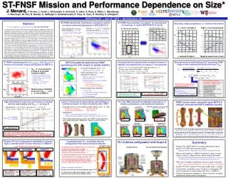
ST-FNSF Mission and Performance Dependence on Device Size. J. Menard 1 T. Brown 1 , J. Canik 2 , L. El-Guebaly 3 , S. Gerhardt 1 , A. Jaber 3 , S. Kaye 1 , E. Meier 4 , L. Mynsberge 3 , C. Neumeyer 1 , M. Ono 1 , R. Raman 5 , S. Sabbagh 6 ,

E N D
ST-FNSF Mission and Performance Dependence on Device Size J. Menard1 T. Brown1, J. Canik2, L. El-Guebaly3, S. Gerhardt1, A. Jaber3, S. Kaye1, E. Meier4, L. Mynsberge3, C. Neumeyer1, M. Ono1, R. Raman5, S. Sabbagh6, V. Soukhanovskii4, P. Titus1, G. Voss7, R. Woolley1, A. Zolfaghari1 1Princeton Plasma Physics Laboratory, Princeton, NJ 08543 2Oak Ridge National Laboratory, Oak Ridge, TN, USA 3University of Wisconsin, Madison, WI, USA 4Lawrence Livermore National Laboratory, Livermore, CA, USA 5University of Washington, Seattle, WA, USA 6Columbia University, New York, NY, USA 7Culham Centre for Fusion Energy, Abingdon, Oxfordshire, UK 17th International Spherical Torus Workshop University of York 16-19 September 2013 This work supported by the US DOE Contract No. DE-AC02-09CH11466
Outline • Motivation for study • Physics basis for operating points • Performance vs. device size • Tritium breeding ratio calculations • Divertorpoloidal field coil layout and design • Power exhaust calculations • Maintenance strategies • Summary
Successful operation of upgraded STs (NSTX-U/MAST-U) could provide basis for design, operation of ST-based FNSF • Fusion Nuclear Science Facility (FNSF) mission: • Provide continuous fusion neutron source to develop knowledge-base for materials and components, tritium fuel cycle, power extraction • FNSF CTF would complement ITER path to DEMO M. Peng et al., IEEE/NPSS Paper S04A-2 - 24th SOFE Conf. (2011) • Studying wide range of ST-FNSF configurations to identify advantageous features, incorporate into improved ST design • Investigating performance vs. device size • Require: Wneutron ≥ 1 MW/m2, test area ≥ 10 m2, volume ≥ 5 m3 M. Abdou et al. Fus. Technol. 29 (1996) 1
Outline • Motivation for study • Physics basis for operating points • Performance vs. device size • Tritium breeding ratio calculations • Divertorpoloidal field coil layout and design • Power exhaust calculations • Maintenance strategies • Summary
ST-FNSF equilibrium inductance, elongation based on values achieved/anticipated in NSTX/NSTX-U • NSTX A=1.7, li = 0.45 – 0.7 plasmas can operate stably at k ~ 2.7 – 2.9 • Expect to improve n=0 control in NSTX-U • Anticipate k 3 possible in NSTX-U/FNSF • Most probable NSTX thermal pressure peaking ~ 1.7 – 2.2 • If similar in NSTX-U/FNSF full non-inductive li ~ 0.45 – 0.7 (BS + NBI)
ST-FNSF free-boundary elongation is reduced with increasing li to match NSTX/NSTX-U trends ST-FNSF equilibrium k versus li ST-FNSF plasma boundaries
ST-FNSF operating point of fGreenwald = 0.8, H98y,2=1.2 chosen to be at/near values anticipated for NSTX-U • H98y,2 1.2 accessed for a range of Greenwald fractions in NSTX • However, much more research needs to be carried out in NSTX-U to determine if H = 1.2 can be achieved reliably • Note: H98y,2 ~ 1 would require much higher Paux (~1.8×) • Need to assess feasibility of access to H98y,2 ~ 1.2 at k ~ 2.7-2.9 in NSTX-U
NSTX disruptivity data informs FNSF operating point with respect to global stability • Increased disruptivity for q* < 2.7 • Significantly increased for q* < 2.5 • Lower disruptivity for bN = 4-6 compared to lower bN • Higher bN increases fBS, broadens J profile, elevates qmin • Operation above no-wall limit aided by: • NBI co-rotation • Close-fitting conducting wall • Active error-field and RWM control • Strong shaping also important • S q95 IP/aBT • S > 30 provides strongest stabilization • S > 22-25 good stability • S < 22 unfavorable
Outline • Motivation for study • Physics basis for operating points • Performance vs. device size • Tritium breeding ratio calculations • Divertorpoloidal field coil layout and design • Power exhaust calculations • Maintenance strategies • Summary
Increased device size provides modest increase in stability, but significantly increases T consumption • Scan R = 1m 2.2m (smallest FNSF pilot plant with Qeng ~ 1) • Fixed average neutron wall loading = 1MW/m2 • BT = 3T, A=1.7, k=3, H98 = 1.2, fGreenwald = 0.8 • 100% non-inductive: fBS = 75-85% + NNBI-CD (ENBI=0.5MeV JT60-SA design) • Larger R lowers bT & bN, increases q* • Comparable/higher bT and bN values already sustained in NSTX • Q = 1 3, Pfusion = 60MW 300MW 5× increase in T consumption
Beyond neutron wall loading and T breeding, FNSF study is also tracking electrical efficiency Qeng Electricity produced Electricity consumed th= thermal conversion efficiency aux = injected power wall plug efficiency Q= fusion power / auxiliary power Mn= neutron energy multiplier Pn= neutron power from fusion P= alpha power from fusion Paux= injected power (heat + CD + control) Ppump= coolant pumping power Psub= subsystems power Pcoils= power lost in coils (Cu) Pcontrol= power used in plasma or plant control that is not included in Pinj Pextra= Ppump + Psub + Pcoils + Pcontrol Note: blanket and auxiliary heating and current-drive efficiency + fusion gain largely determine Qeng FNSF assumptions (from Pilot study): • Mn = 1.1 • Ppump = 0.03×Pth • Psub + Pcontrol = 0.04×Pth • haux = 0.4 (presently unrealistically high) • hCD = ICDR0ne/PCD = 0.3 × 10²⁰A/Wm2 For more details see J. Menard, et al., Nucl. Fusion 51 (2011) 103014
High performance scenarios can access increased neutron wall loading and Qeng > 1 at large R • Decrease BT = 3T 2.6T, increase H98 = 1.2 1.5 • Fix bN = 6, bT = 35%, q* = 2.5, fGreenwald varies: 0.66 to 0.47 Pelectric produced Pelectric consumed Qeng Note: Outboard PF coils are superconducting • Size scan: Q increases from 3 (R=1m) to 14 (R=2.2m) • Average neutron wall loading increases from 1.8 to 3 MW/m2 (not shown) • Smallest ST for Qeng ~ 1 is R=1.6m requires very efficient blankets
Outline • Motivation for study • Physics basis for operating points • Performance vs. device size • Tritium breeding ratio calculations • Divertorpoloidal field coil layout and design • Power exhaust calculations • Maintenance strategies • Summary
Cost of T and need to demonstrate self-sufficiency motivate analysis of tritium breeding ratio (TBR) • Example costs of T w/o breeding at $0.1B/kg for R=1 1.6m • FNS mission: 1MWy/m2 $0.33B $0.9B • Component testing: 6MWy/m2 $2B $5.4B • Implications: • TBR << 1 likely affordable for FNS mission with R ~ 1m • Component testing arguably requires TBR approaching 1 for all R • Performed initial analysis of R=1.6m FNSF using conformal and straight blankets, ARIES-ST neutron source profiles: 5% 32% Neutron Source 63%
R=1.6m TBR calculations highlight importance of shells, penetrations, and top/bottom blankets Extended conformal + 3cm shell + NBI Extended conformal blanket NBI penetration at midplane + 3cm thick stabilizing shell Stabilizing shell TBR = 1.02 10 NBI penetrations TBR = 1.1 TBR = 1.07 Extended straight blanket Straight blanket with flat top Conformal blanket Straight blanket TBR = 1.047 TBR = 1.0 TBR = 0.8 TBR = 1.046
Outline • Motivation for study • Physics basis for operating points • Performance vs. device size • Tritium breeding ratio calculations • Divertorpoloidal field coil layout and design • Power exhaust calculations • Maintenance strategies • Summary
FNSF center-stack can build upon NSTX-U design, incorporate NSTX stability results • Like NSTX-U, use TF wedge segments (but brazed/pressed-fit together) • Coolant paths: gun-drilled holes or NSTX-U-like grooves in wedge + welded tube • Bitter-plate divertor PF magnets in ends of TF enable high triangularity • NSTX data: High d > 0.55 and shaping S q95IP/aBT > 25 minimizes disruptivity • Neutronics: MgO insulation can withstand lifetime (6 FPY) radiation dose
Outline • Motivation for study • Physics basis for operating points • Performance vs. device size • Tritium breeding ratio calculations • Divertorpoloidal field coil layout and design • Power exhaust calculations • Maintenance strategies • Summary
Divertor PF coil configurations identified to achieve high d, maintain peak divertor heat flux ≤ 10MW/m2 Field-line angle of incidence at strike-point = 1˚ • qpeak ~ 10MW/m2 • Flux expansion = 15-25 • 1/sin(qplate) = 2-3 • Rstrike = 1.15m, dx ~ 0.55 Super-X Conventional Snowflake • qpeak ~ 10MW/m2 • Flux expansion = 40-60 • 1/sin(qplate) = 1-1.5 • Rstrike = 1.05m,dx ~ 0.62 • qpeak ~ 3MW/m2 • Flux expansion = 2 • 1/sin(qplate) = 15 • Rstrike = 2.6m,dx ~ 0.56
Combined super-X + snowflake divertorconfiguration has many attractive features li= 0.82 k = 2.55 • Outboard PF coils shielded by blankets can be SC • Increased strike-point radius to reduce B and q||, further increase line-length • Strike-point PFCs shielded by blankets • 2nd X-point/snowflake lowers BP, increases line-length • Possible location for T breeding to increase TBR • PF coil design supports wide range of li values (0.4 – 0.8) with fixed strike-point location/region and controllable B-field angle of incidence (0.5-5˚) Normally conducting PF coil features: • Divertorcoils in TF coil ends for equilibrium, high d • In-vessel coils not-required for shaping – will be used for vertical control (to be studied in future) li= 0.40 k = 3.0
Super-X ~3× reduction in qpeak: 10 3MW/m2 for fixed radiation fraction and angle of incidence
R=1.6 device configuration with Super-X Design features Vertical maintenance approach S/C PF coils housed in VV upper lid S/C PF coils pairs located in common cryostat VV outer shell expanded to add shield material Angled DCLL concentric lines to external header S/C PF coils housed in VV lower shell structure Reshaped TF leads
Summary • Present STs (NSTX, MAST) providing preliminary physics basis for ST-FNSF performance studies • Upgraded devices will provide more extensive and definitive basis • Neutron wall loading of 1MW/m2 feasible for range of major radii for b and H98 values at/near values already achieved • High wall loading and/or pilot-level performance require bN ~ 6 and H98 ~ 1.5 which are at/near maximum values attained in present STs • TBR near 1 possible if top/bottom neutron losses minimized • TBR ≥ 1 may only be possible for R ≥ 1.6m – under active investigation • Divertor PF coils in ends of TF bundle enable high d, shaping • Conventional, snowflake, super-X divertors investigated, PF coils incorporated to reduce peak heat flux << 10MW/m2 • Vertical maintenance strategies for either full and/or toroidally segmented blankets being investigated
Future work • Physics basis for operating points • Perform sensitivity study of achievable performance vs. baseline configuration assumptions: A, k, H98y,2, ST vs. tokamaktE scaling • TRANSP calculations of NBI heating, current drive, neutron production • Performance vs. device size • Could/should overall machine configuration change at smaller R? • Example questions: could/should vessel take more load? • Is there sufficient shielding for divertor PF coils at smaller R? • Tritium breeding ratio calculations • Extend calculations to smaller R • Include 3D effects and final machine layout • Maintenance strategies • Assess space/lift requirements above machine for vertical maintenance
Boundary shape parameters vs. internal inductance High d = 0.5-0.6 maintained A = 1.81.7 at higher li k reduced at higher li • Negative squareness at lowli
Bitter coil insert for divertor coils in ends of TF Insulator Glidcop plates
Neutronics analysis indicates organic insulator for divertor PF coils unacceptable
MgO insulation appears to have good radiation resistance for divertor PF coils • UW analysis of divertor PFs • 1.8x10¹²rad = 1.8x10¹⁰Gy at 6FPY for Pfus = 160MW • Pilot mission for R=1.6m: • Pfus = 420MW vs. 160MW 2.6x higher 4.7x10¹⁰Gy • Even for Pilot mission, dose is < limit of 1011Gy • Limiting factor may be Cu • Need to analyze CS lifetime • Revisit option for multi-turn TF and small OH solenoid