Download
1 / 20
200 likes | 371 Views
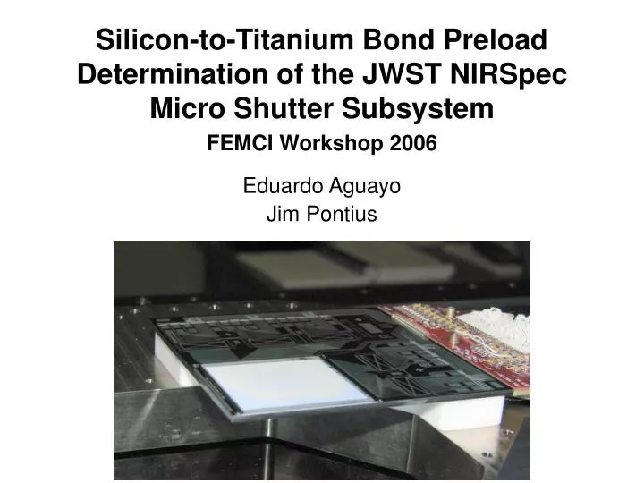
Silicon-to-Titanium Bond Preload Determination of the JWST NIRSpec Micro Shutter Subsystem. FEMCI Workshop 2006 Eduardo Aguayo Jim Pontius. Introduction.

E N D
Silicon-to-Titanium Bond Preload Determination of the JWST NIRSpec Micro Shutter Subsystem FEMCI Workshop 2006 Eduardo Aguayo Jim Pontius
Introduction • The Micro-Shutter Subsystem (MSS) has been developed to provide the capability of multi-element spectroscopy to the James Webb Space Telescope (JWST) • The MSS houses four shutter arrays, each with over 64,000 shutters that can be addressed individually to allow (when open) or block (when closed) a portion of the sky • Each micro-shutter array is bonded to a silicon substrate which is in turn bonded to three titanium flexures • The flexures are part of a flexure plate which is in turn bolted to a base plate • This sub-assembly is known as a quadrant • The silicon-to-titanium bonds are of particular concern • In order to avoid excessive dynamic loading of the bonded joints and displacement of the substrate during launch loads, the substrate has been preloaded • Preload is accomplished by placing a slightly oversized Teflon snubber between the silicon substrate and the base plate • However, this preload imparts moments and a tensile force on the bonded joints • Currently an experimental unit has been developed to test the silicon-to-titanium bonds • This unit is composed of a Titanium base plate, Titanium Flexure plate, a Full Quadrant Sub-Assembly and Mass Dummies (Each dummy represents a full quadrant sub-assembly)
Micro-shutter Array Silicone substrate Quadrant Sub-Assembly Bond Pad Flexure Base plate Teflon snubber Flexure Plate Mass dummy (each represents a quadrant assembly)
Silicon Substrate Micro-Shutter Array Base Plate Teflon
Environmental Requirements • Sine burst (quasi-static load): 42g • Random vibration:
FE Model 30,865 Nodes 29,088 Elements Bar Elements Spring Elements Plate Elements Solid Elements Mass Elements Rigid Elements
Analytical Process Steps • Obtain 3-Sigma acceleration at the c.g. of the substrate • Compare the 3-sigma acceleration induced by random vibration at the c.g. of the substrate to quasi-static loads • Whichever one is higher is the critical design case • The total preload must be equal to the critical acceleration times the mass of the substrate • The preload is obtained by mounting the substrate on top of an oversized Teflon snubber • The Teflon snubber has an overlap • The overlap is derived using methods explained herein • Too much preload can damage the bond, and thus a maximum overlap must also be prescribed
Teflon Snubber Concept d Silicon Substrate Teflon Snubber Titanium Flexure height Base Plate • The following picture shows a cross section of the base plate, flexure and silicon substrate compared to the Teflon snubber before it is placed between the silicon substrate and the base plate • Notice that the Snubber is oversized by a distance d (which has been exaggerated in the picture) • The oversize will be referred to as “overlap”
Note on Flexure Detail • The flexures have a vertical blade to accommodate the cool down to cryogenic temperatures while assuring that strict alignment requirements are met • The flexures have a smaller horizontal blade • This causes the flexures to be soft in the vertical direction • This allows for a more measurable overlap Bond Pad Horizontal Blade Vertical Blade Flexure Plate
Silicon Substrate Flexure Teflon Snubber Base Plate • When the Teflon snubber is put in between the silicon substrate and the base plate, the overlap will induce a preload: • The deformations have been exaggerated for clarity
Random Response • Random Vibration Analysis was ran using NASTRAN • Semi-Empirical method was used to force limit (C was chosen such that the c.g. acceleration of the structure would be equal to the design limit load of 42.5g): • During the random response analysis it was assumed that the preload was enough to avoid gapping between the Teflon snubber and the Silicon substrate • Spring elements were used to “attach” the substrate to the snubber only in the z-direction
The random response acceleration for the c.g. of the substrate is • Grms: 13.36 • 3-Sigma Grms: 40.08g
Preload Calculation • The mass of the substrate is 34.4 grams • Acceleration imparted on substrate during random assumed to be 40.08g • Acceleration imparted during sine burst is 42g • Therefore the total preload must be 34.4 grams x 42g = 14.17 N = 3.19 lb
Teflon “Overlap” Calculation • How much load is caused at each bond pad by the extra overlap of Teflon ? • By applying a thermal load only to the Teflon, so that the Teflon grows a known amount, it is possible to answer this question • Set reference temperature for all materials, except Teflon, to 1 • Set reference temperature for Teflon to 0 • Apply a uniform temperature load to the entire structure of 1, so that only the Teflon will see a temperature change • Assume the CTE of Teflon to be 1 which means that by applying a change in temperature of 1 the Teflon snubber would double in height if it were completely unconstrained • The unconstrained change in height, or growth, is equal to the “overlap” that causes the preload • Note that the actual displacement of the Teflon under the Silicon substrate will vary across the surface of the Teflon, and thus is not equal to the unconstrained change in height • Obtain: • Silicon substrate stresses • Titanium flexure stresses • Bond pad loads and stresses • Scale results so that the change in temperature applied to the Teflon causes Bond pad loads equal or greater than the necessary preloads obtained earlier
A temperature change of 1 in the Teflon causes the following: • Max stress in the substrate: 456 ksi • Max stress in the flexures: 3,028 ksi • Max bond stress: 69.5 ksi • Total preload: 1,047 lb • Nominal overlap: 11.66 mm (equal to the height of the Teflon) • Scale the results so that the total preload is equal to 3.19 lb • Max stress in the substrate: 1.38 ksi • Max stress in the flexures: 9.19 ksi • Max bond stress: 211 psi • Total preload: 3.19lb • Nominal overlap: 1.39 mil • Therefore the Teflon snubber must have an overlap of at least 1.39 mil to avoid gapping • Since there is very little damping, 6-Sigma events could be possible, therefore it is desirable to have a comfortable margin of safety on the preload • But too high of a preload will cause problems in the bond
Contour Plots The stresses in the Silicon Substrate were monitored closely. Since single crystal silicon is a brittle material, small imperfections greatly reduce the material allowables. Therefore it is desirable to keep the principal stresses in the silicon substrate under 6 ksi. Although titanium is a very strong metal, it was still necessary to make sure that the stresses caused in the flexures by the preload were within the material allowables.
It is desirable to keep the stresses in the bond low • Avoid bond failure due to high preload • Avoid unexpected failure modes, such as creep • Therefore, aim to maintain stresses in the bond below 650 psi (somewhat arbitrary value) • Now Scale the results so that the max stress in the bond is 650 psi • Max stress in the substrate: 4.27 ksi • Max stress in the flexures: 28.32 ksi • Max bond stress: 650 psi • Total preload: 9.79lb • Nominal overlap: 4.29 mil • Therefore the Teflon snubber must have an overlap smaller than 4.29 mil
Nominal Overlap • The Teflon snubber must have an overlap greater than 1.39 mil and less than 4.29 mil • The prescribed nominal overlap has been set to 4 mil which causes a nominal preload of 9.11 lbs • The tolerance is -1/+0.3 mil • This ensures that the preload is at least twice as high as the analytical loads expected, resulting in enough margin to accommodate for analytical errors as well as higher than 3-sigma events • The prescribed overlap (with tolerance) also ensures that the stresses in the bond are well below the allowables so that there is no failure in the bond
Validation of Analytical Results • The nominal overlap was implemented and the experimental unit was tested • Of particular concern was making sure that the analytical predicted accelerations under random vibration were accurate • The following table compares the accelerations at the bond pads obtained from analyses and tests • It is possible to observe that the results agree well, suggesting that the predictions of the FE model are valid • Furthermore, accelerometer data scaled well during testing and there were no non-linearities that would indicate gapping
Conclusion • The overlap of the Teflon snubber must be 4 (-1/+0.3) mil • Ensures that stresses in the flexures, silicon substrate, and bond are within the allowables • Analysis suggests that there will be no gapping for loads up to 84g’s • If there is no gapping the dynamic loads in the bonded joint are greatly reduced, thus mitigating failure • Test data supports analysis • Test data agrees well with analytical predictions • There were no observable non-linearities in the test results • The bonded joint survived the test