Download
1 / 41
410 likes | 603 Views
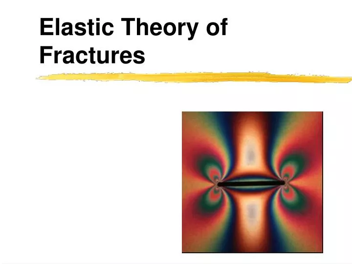
Elastic Theory of Fractures. Idealization of fracture for mechanical analysis. Infinite length in x 3 direction Shape is constant in x 3 direction Homogeneous, isotropic and linear elastic. Stress tensor . Stress tensor at any point depends on Position Geometry of crack

E N D
Idealization of fracture for mechanical analysis • Infinite length in x3 direction • Shape is constant in x3 direction • Homogeneous, isotropic and linear elastic
Stress tensor • Stress tensor at any point depends on • Position • Geometry of crack • Traction on crack faces • Remote state of stress • ij = fij (x1, x2, a and boundary conditions)
Displacements depend on • Position • Crack geometry • Traction on crack faces • Remote stress • Elastic moduli for stress boundary-value problem • ui=gi(x1,x2,a,m,n and boundary conditions) • E=2m (1+)
Definitions • Boundary Value Problem • Stress, displacement and mixed • Traction • Force per unit area on a surface • Cauchy’s formula • Ti=sijnj
How to solve a BVP • Constitutive • Linear-elastic • Equilibrium • Quasi-static • Compatibility • Can combine with constitutive relations to get harmonic form for first stress invariant
Solving the system in 2D • 3 equations • 2 equilibrium • 1 compatibility • 3 unknowns • Plane strain: s11, s12, s22 • Boundary conditions for cracks • Stresses must match the far-field at x1 or x2 -> ∞ • Stresses must match crack-face tractions tractions at x1=0+, |x2|≤a
Airy’s stress function • U=U(x1, x2, a, sr11, sr12, sr22, sc11, sc12) • If U has the following relations, the equilibrium conditions are satisfied • Substitute these into compatibility and get biharmonic for U
Making the Airy’s stress function (even more) complex • Muskhelishvili: The Airy stress function can be expressed as two functions of the complex variable • Z ? • Re[ ] ? Im[ ] ? • Why? To make finding solutions easier. Nikoloz Muskhelishivili
Using the complex Airy’s functions • Take derivatives of the Airy’s stress functions to get stresses • Use constitutive relations to get strains • Then find f and to match boundary conditions
Westergaard function • H. M. Westergaard (1939): reduced the two unknown functions to one function, m , for a crack using symmetry
The stress function • fm(z) = Am[(z2-a2)1/2-z] + Bmz DsI (s11r-s11c) 1/2(s11r+s22r) Am= -iDsII = -i(s12r-s12c ) Bm= 0 -iDsIII -i(s13r-s13c) s23r-is13r • First part:crack contribution • Second part: remote load contribution
But aren’t there simpler equations out there? • Simpler relations have been developed for the stress fields near crack tips. • The Westergaard function gives the stress field everywhere including the crack tips.
Boundary Element Method Becker 1992. The Boundary Element Method in Engineering: A Complete course, Mc Graw Hill Crouch and Starfield, 1990 Boundary Element Method in Solid Mechanics with applications in rock mechanics and geological engineering, Unwin Hyman
Discretization • Deformation of each small bit within the body is solved analytically • Putting the bits together relies on computation power of modern processors • Consider influence of neighboring bits • Principle of superposition • Discretization introduces error • How could you assess or minimize this error?
Solving a BVP • Prescribe • Geometry • Boundary conditions (stress or displacement) • Constitutive properties • Solve for stress and displacement/strain throughout the body • Solution must be true to prescribed conditions
What are the different methods? • Finite Element Method (FEM) • Boundary Element Method (BEM) • Discrete Element Method (DEM) • Finite Diffference Method (FDM) From Becker
Finite element method • Approximates the governing differential equations by solving the system of linear algebraic equations • Mesh the body into equant volumetric or planar elements • Computationally expensive with fine grids but has a sparse stiffness matrix • Handles heterogeneous materials well
Boundary element method • Governing differential equations are transformed into integrals over boundaries. These integrals are expressed as a system of linear algebraic equations. • Boundaries discretized into linear or planar equal sized elements • Computationally cheaper than FEM (fewer elements) but has a full and asymmetric matrix • Clunky for heterogeneous materials
Discrete Element Method • Caveat: only use when contact mechanics dominate the deformation • Does not incorporate stress singularity at crack tips • Discretizes the body into particles in contact • Analyzes the contact mechanics between each particle • Computationally expensive with many elements • Handles heterogeneity very well • Useful for specific problems e.g. fault gouge, deformation bands
Finite Difference Method • Solves governing differential equations by differencing method • Mesh the body -- solves at internal points • Computationally cheap and easy to program • Cannot accurately incorporate irregular geometries or regions of stress concentration • Appropriate for contact problems,heat and fluid flow
Which method best for fractures? • Capturing the 1/r1/2crack tip singularity • Fracture propagation
Crack tip singularity • Finite Element? • Special grid designed to capture the 1/r1/2 crack tip singularity • awkward and expensive • Boundary Element? • Each element is a dislocation • A series of equal length dislocations automatically incorporates the r-1/2 crack tip singularity
Fracture Propagation • Finite Element? • Fracture must be remeshed and the special crack tip elements moved to a new location • awkward • Boundary Element? • Add another element to the tip of the fracture
Complicated fracture geometry • Boundary Element is hands down the best
Poly3d • IGEOSS • 3D • Complex fractures • Linear elastic homogeneous rheology • Frictional faults • Nice user interface
Flamant’s solution • Deformation within a half space due to two point loads • One normal • One shear wikipedia
Distributed load • Superpose Flamant’s solution as you integrate over the distributed load
Rigid Die problem • What are the tractions that could produce a uniform displacement? • Displacement along boundary element i due to tractions on all other elements, j=1 to N • Bij is the matrix of influence coefficients • Effects of discretization and symmetry
Fictitious Stress Method • Based on Kelvin’s problem • A point force within an infinite elastic solid • Similar to Flamant’s • Can be used for bodies of any shape • Leads to constant tractions along each element.
Displacement discontinuity method • Constant displacements along each element • Better for bodies with cracks • incorporates the singularity in displacement across the crack
Displacement discontinuity method • Displacement has a 1/r singularity • A series of constant displacement elements replicates the 1/r1/2 stress singularity at the crack tip.
Numerical procedure • The stresses on the ith element due to deformation on the jth element • A is the boundary influence coefficient matrix
Numerical procedure • Sum the effects for all elements
Numerical procedure • If you know displacements (displacement boundary value problem) the solution is found quickly. • If you have a mixed or stress boundary value problem, you need to invert A to find the displacements
Numerical procedure • Once you know displacements and stresses on all elements, you can find the displacements at any point within the body. • Flamant’s solution
Frictional slip • |t|=c-ms • Inelastic deformation • Converge to solution • Penalty Method • Direct solver • Apply a shear and normal stiffness to elements to prevent interpenetration (e.g. Crouch and Starfield, 1990) • Complementarity Method • Apply inequalities • Implicit solver (e.g. Maerten, Maerten and Cooke, 2010)
What about 3D elements • Cominou and Dundurs developed angular dislocation.
Boundary integral method • Uses reciprocal theorem (Sokolnikoff) to solve for unknown boundary conditions.