Download
1 / 12
120 likes | 334 Views
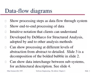
Data-flow Diagrams. Chapter 17. Elements of data-flow diagrams. There are four basic elements of data flow diagrams: Data Transforms : where data is filtered, formatted or synthesized. Information sources and sinks : essentially inputs and outputs to the system.

E N D
Data-flow Diagrams Chapter 17
Elements of data-flow diagrams • There are four basic elements of data flow diagrams: • Data Transforms: where data is filtered, formatted or synthesized. • Information sources and sinks: essentially inputs and outputs to the system. • Information stores: where information is kept for the duration of system activity. • Information Flows: data that is passed into and out of transforms, information stores.
Information flows • Information flows represent the information being passed into or out of a transform, source, sink or store. It is represented as a labeled arrow: Taxable Income
Data transforms • Data transforms labeled circles with one or more incoming and outgoing information flows: Taxable Income Tax owed Calculate Tax Tax Tables
Information sources and sinks • Information sources and sinks are information that come into the system, or leave the system, and are represented by squares: Pay Stub Hours Payroll System Pay Check Rate
Information stores • Information Stores represent locations where information can be store for the duration of the system activity: Total Payroll Expense
Refining DFDs • DFDs are “refined” (decomposed) to the point that they are contain only “primitive” transforms. They are refined by drawing another DFD as if they were a system in themselves! • A “primitive” transform has only one input flow or only one output flow (note that it can have multiple input flows or multiple output flows, but not both!)
Heritage numbers • Refinement of DFDs leads to a problem in larger systems: we have a large number of diagrams! When we look at a diagram by itself the only way we can tell what it represents is by looking at the parent diagram. • Heritage numbers allow this. A data transform numbered 2.4.3 is the child of DFD number 2.4 which is the child of DFD 2 in the level 1 DFD diagram.
The data dictionary • As the data is defined in the DFD (the flows), definitions should be entered in the ‘data dictionary’. • The ‘data dictionary’ is a reference that allows us to determine the type of the named data (int, float, struct, whatever.) • This will be essential during the programming phase, when knowing what variable names to use.
Checking DFDs - CASE tools • Since DFDs are a formal method, tools have been developed that allow automated drawing of the DFDs, and management of refined DFDs. • Since this can be automated, checking DFDs can also be automated (such as ‘Process Analyst’).
Structure charts • Translation of a DFD to a ‘structure’ chart is a mechanical procedure (see the book.) • The procedure involves ‘isolating’ the central transform area, which is independent of the format transforms and the validation transforms. • Structure charts also provide a schematic showing the flow of the data in a control diagram! • Now we have a complete picture: DFDs show how the data flows, and structure charts show how control is passed!
Implementing a DFD • Once we have a structure chart, the actual implementation also becomes mechanical. An essential pre-defined form becomes apparent for implementing structure charts. An example using C is available in the book.