Download
1 / 33
360 likes | 384 Views
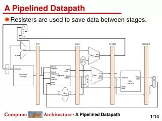
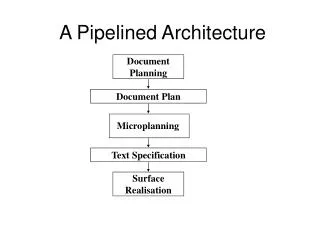
A Fully Pipelined and Dynamically Composable Architecture of CGRA. Faculty: Jason Cong Project members: Hui Huang, Chiyuan Ma, Bingjun Xiao, Peipei Zhou* VAST Lab Computer Science Department University of California, Los Angeles. Computing Beyond Processors. CPU

E N D
A Fully Pipelined and Dynamically Composable Architecture of CGRA Faculty: Jason Cong Project members: Hui Huang, Chiyuan Ma, Bingjun Xiao, Peipei Zhou* VAST Lab Computer Science Department University of California, Los Angeles
Computing Beyond Processors • CPU • General purpose computing solution • Sharing hardware among all instructions • Low energy efficiency • ASIC • Customized for dedicated applications • High efficiency but no flexibility • FPGA • Configurable at bit level to keep both efficiency and flexibility • CGRA • Programming granularity to word level most applications use full precision • Reduce configuration information and enable on-the-fly customization
Conventional CGRA • CGRA • Transistor resources are scarce in the past • Each PE contains configuration RAM to store the multiple instructions • Now transistor resources are rich -> Primary target changes: Energy efficiency Source: Hyunchul Park etl, Polymorphic Pipeline Array: A Flexible Multicore Accelerator with Virtualized Execution for Mobile Multimedia Applications, 2009 Micro
Full Pipelining with Rich Transistor Resources • When pipeline initial interval increases 1 2, resource does not reduce by 50% • When an accelerator achieves II=1, i.e., each input/output consumes/produces a new data/cycle the highest performance/area our design principle • Insights • Time multiplexing costs resource to store more pipeline states and switch data paths • When there are rich transistor resources, no need to suffer these overheads Resource (normalized) Performance/Area: Words/Second /Slice Pipeline Initial Interval (II)
Dynamic Composition with Rich Transistors • Dynamically Composition • (a) Compose accelerators for two applications from the reconfigurable array • (b) Duplicate multiple copies of accelerators for a single application APP1 APP1 APP1 APP2 APP1
Outline • Programming Model • Architecture Overview • Computation Complex • Case Study • Experiment Result • Conclusion and Future Work
What Programming Model Can Be Mapped? prefetch data block from offchip load load load load load + + + + Iterate over elements in a data block processed by inner loops x x x x + + Iterate over different data blocks + Loop is the key! Focus on loop acceleration, without inter-loop dependencies store write back data block to offchip
Outline • Programming Model • Architecture Overview • Computation Complex • Case Study • Experiment Result • Conclusion and Future Work
Complete System Design • FPCA(Fully Pipelined and Dynamically Composable Architecture of CGRA) architecture overview • The host process will execute the general-purpose operations • Also send the computation tasks to the global accelerator manager(GAM) *. • Array of processing element (PE) clusters *:Source: J. Cong et al. CHARM: A Composable Heterogeneous Accelerator-Rich Microprocessor, ISLPED 12
Overview of Our Composable Accelerator Composable Accelerator Computation Complex ……… CE CE CE [31:0]Pipelined Data Network Configuration Unit Data flow though @ II=1 ……………………… … … Memory Complex ……… LMU LMU LMU Register Chain Register Chain ……… Synchronization Unit Global Data Transfer Unit Controller GAM AXI data bus IOMMU
Outline • Programming Model • Architecture Overview • Computation Complex • Case Study • Experiment Result • Conclusion and Future Work
Computation Complex Computation Complex Pn-1 Pn ……… CE CE CE An Bn Cn Dn Pout operators can be skipped by configuration [31:0] Pipelined Data Network + + + + CE CE x x x x + + CE CE +
Outline • Programming Model • Architecture Overview • Computation Complex • Case Study • Experiment Result • Conclusion and Future Work
Case Study of Data Flow t=0 1 2 3 4 5 6 7 8 9 10 11 Computation Complex tmp0 tmp2 tmp1 +(c-u)2 (c-r)2 +…+(c-l)2 (c-d)2 CE CE CE CE CE CE b[1][1] a[1][1] Permutation Data Network a[1][1] a[1][1] a[1][1] 32-bit, fully pipelined, configured upon accelerator composition LMU LMU LMU LMU LMU LMU Register Chain Register Chain … a[1][2] a[0][1] a[2][1] a[1][1] a[1][0] On-Chip Memory Complex l: a[j][k-1] r: a[j][k+1] u: a[j-1][k] d: a[j+1][k] c: a[j][k] b[j][k]
Case Study of Data Flow Computation Complex +(c-u)2 (c-r)2 +…+(c-l)2 (c-d)2 CE CE CE CE CE CE b[1][1] b[1][2] No Flow Control Here b[1][3] b[1][4] Permutation Data Network 32-bit, fully pipelined, configured upon accelerator composition LMU LMU LMU LMU LMU LMU Register Chain Register Chain … a[1][7] a[1][6] a[1][5] a[1][3] a[1][4] a[1][2] a[0][5] a[0][2] a[0][1] a[0][6] a[0][4] a[0][3] a[2][1] a[2][3] a[2][5] a[2][2] a[2][6] a[2][4] a[1][5] a[1][6] a[1][4] a[1][1] a[1][3] a[1][2] b[1][1] a[1][1] a[1][4] a[1][2] a[1][5] a[1][3] a[1][0] b[1][2] countdown: 3 countdown: 2 countdown: 1 countdown: 0 b[1][3] On-Chip Memory Complex left right up down center output
Putting Them Together • Takes 4 CEs, 6 LMUs and a register chain • Associated with 16872 LUTs (c-d)2 +(c-r)2 (c-u)2 +…+(c-l)2 left right up down center output
Outline • Programming Model • Architecture Overview • Computation Complex • Case Study • Experiment Result • Conclusion and Future Work
Experiment Results • Composition time VS Run time: • Xilinx ML605 FPGA Board • 256*256*256 3D image, 100MHz frequency bitstream download time: 20s
Experiment Results • Run time: • Xilinx ML605 FPGA Board • 256*256*256 3D image, 100MHz frequency Projection based on: I.Kuon etl “Measuring the Gap Between FPGAs and ASICs”, IEEE Transaction on Computer-Aided Design of Integrated Circuits and Systems, vol. 26, no. 2, pp. 203—215 Feb, 2007
Area Breakdown • Slice Register and Slice LUTs for each module
Outline • Programming Model • Architecture Overview • Computation Complex • Case Study • Experiment Result • Conclusion and Future Work
Conclusion & Future Work • A Novel CGRA Architecture Enables • Full pipelining • Dynamic composition • Future Work • CE: The selection of computation patterns for different domains • Heterogeneous or Homogeneous CE design • Reduce overhead of composition
Thank you • Q&A?
Back Up Slides • Compared to VLIW • Difference • There is no routing problems for VLIW since all FUs can read from register file
Case Study of Execution Flow task list task 0~20 to_IOMMU (page translation) Initiator Controller data transfer request of A0 data transfer request of A1 data transfer request of A2 from_IOMMU (DMA packet) data transfer request of B0 Monitor data transfer request of B1 DMA: tile B0 data transfer request of B2 DMA: tile B1 tile A0 DMA: tile A0 DMA: tile A1 DMA: tile A2 DMAC Bus to external memory tile A2 tile A1 !full write commit !empty read commit cmp… cmp… tileB0 tile B1 ……… LMU (a) LMU (b) cmp… cmp… read start ready (!full) write start ready (!empty) Synchronization Unit
Computation Element (CE) • Execute computation with pattern: • 3 cycles latency always assumed from any input • Configuration bit protocol • Constant configuration bits provided during operation, 8 bits • Config[6:5], stage1 = A+D when 1, A-D when 2, A otherwise • Config[4:3], stage2 = B * stage1 when 1, stage1 * stage1 when 2, stage1 otherwise • Config[2:0], output Pn = stage2 + C when 1, Pn-1 + stage2 when 2, Pn-1 + stage2 + C when 3, Pn-1 – stage2 when 4, Pn-1 – stage2 + C when 5, stage2 otherwise • Config[7], output Pn is further buffered for {0,1} * delay(CE) cycles Configuration bits stage1 stage2 Pn An Pn-1 Pn +/- +/- FF FF FF FF xFF * CE An Bn Cn Dn FF 2 FFs 3 FFs 3 FFs Dn Bn Cn Pn-1
Composition of Computation Complex • Pattern supported by computation element • Found lots of computation patterns follow: • add, then multiply, then add • Adjacent CEs are chained to save interconnects • Also matches Xilinx DSP block + + + + x x x x + + Configuration bits stage1 stage2 + Pn An Pn-1 Pn +/- +/- FF FF FF FF xFF * CE An Bn Cn Dn FF 2 FFs 3 FFs 3 FFs Dn Bn Cn Pn-1
Composition of Data Network • Connections among computation elements (also on-chip memories) can be arbitrary • However most edges are single fan-out • Use one-to-one permutation network to connects them together • Reconfigure the network only when composing accelerators • Pseudo scalable with # of inputs and outputs • # of switches = (2log(x)-1)x CE CE CE CE
Composition of Registers • Enable • data duplication to match CE fanout in data flow graph • configurable delays to synchronize CE inputs • Motivation example: r*(r*(r+0.2)+0.1) • Adjacent register chains can be further chained to • provide even larger fanout • provide even longer delay Configuration bits Inprev In Out0 Out1 Out2 Out3 Register Chain
Composition of On-Chip Memories • To avoid memory contention, load operations of different addresses different local memory units • Each local memory unit contains a dedicated address generator to • generate a new address every clock cycle, and read (or write) data from on-chip memory, and send to computation element through the permutation network • The iteration domain of address generator is configured upon composing accelerators u[j][k+1] u[j-1][k] u[j][k-1] u[j][k] u[j+1][k] load load load load load LMU LMU LMU LMU LMU
Composition of Global Memory Controllers • Data transfer initiator • iterate over a task list of image tiles, generate and send data transfer request to IOMMU • keep generating requests until > 10 requests sent but yet to finish • IOMMU monitor • receive DMAC requests (physical addresses, page wise), distribute to channel queues • DMAC • if empty/full signal from LMUs is ‘0’ and exists a request in queue for each channel, execute DRAM/LMU memcpy • Select MUX • Multicast a var to multiple LMUs to_IOMMU Initiator Controller to LMUs from_IOMMU Monitor queue per channel DMAC each variable array occupies a channel AXI data bus to DRAM
Mapping Example • Takes 4 CEs, 6 LMUs and a register chain • Associated with 16872 LUTs (c-d)2 (c-r)2 +(c-u)2 +…+(c-l)2 left right up down center output to fetch left, start_addr = 6 length = 3, copy = 3, stride = 5
On-Board Experimental Results • Accelerator kernel: gradient in denoise • Image size 128x128x128 • Note that composable accelerators can compose all resources for as many instances as possible due to flexibility • residual resources can be composed to 5 more gradient kernels • results are projected due to contention on limited FPGA pins to DRAM