Download
1 / 27
270 likes | 512 Views
Gamma-ray Large Area Space Telescope. GLAST Large Area Telescope LAT Pre-Shipment Review EMI/EMC Michael Lovellette, Test Director Naval Research Lab. EMI/EMC The Bottom Line . No emissions excesses found in any LAT system level test, CE or RE One susceptibility found

E N D
Gamma-ray Large Area Space Telescope GLAST Large Area Telescope LAT Pre-Shipment Review EMI/EMC Michael Lovellette, Test Director Naval Research Lab EMI/EMC
EMI/EMC The Bottom Line • No emissions excesses found in any LAT system level test, CE or RE • One susceptibility found • Tracker occupancy specification of <10-4 violated at ~100 MHz vertical polarization in RS • Nothing on the vehicle radiates in this frequency band • Also unlikely for external radiation • Not considered a problem, waiver submitted • EMI report in preparation, LAT-TD08585-01 EMI/EMC
Purpose / Contents • Demonstrate LAT complies with all EMI/EMC requirements: • Conducted and radiated emissions below required levels • LAT does not exhibit susceptibilities when exposed to conducted or radiated energy at required levels • Test Categories • Conducted emissions (CE) • Radiated emissions (RE) • Conducted susceptibility (CS) • Radiated susceptibility (RS) • Requirements flowdown • Mission System Spec 433-SPEC-0005 • LAT Environmental Requirements Spec LAT-SS-00778 • LAT Performance Verification Plan LAT-MD-00408-04c • EMI Test Plan LAT-MD-02726-02 EMI/EMC
Subsystem EMI/EMC Test Summary EMI/EMC
Radiator Subsystem EMI/EMC Test • VCHP heater Radiated Emissions testing • S/C power source for LAT VCHP heaters is an unfiltered DC-DC converter. • Concern is the conducted noise for this power source will become radiated emission issue for LAT system test. • This issue shall be resolved by special subsystem (Radiator) test – RE102 – using simulated S/C power source. • The test was performed just prior to LAT RE102 test. • Not formally part of the LAT level EMI test, performed on an STR EMI/EMC
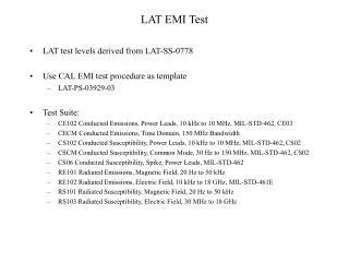
LAT EMI Test LAT test levels derived from LAT-SS-0778 • Test Suite: • CE102 Conducted Emissions, Power Leads, 10 kHz to 10 MHz, MIL-STD-462, CE03 • CECM & CEDM* Conducted Emissions, Time Domain, 150 MHz Bandwidth • CS102 Conducted Susceptibility, Power Leads, 10 kHz to 10 MHz, MIL-STD-462, CS02 • CSCM Conducted Susceptibility, Common Mode, 30 Hz to 150 MHz, MIL-STD-462, CS02 • CS06 Conducted Susceptibility, Spike, Power Leads, MIL-STD-462 • RE101 Radiated Emissions, Magnetic Field, 20 Hz to 50 kHz • RE102 Radiated Emissions, Electric Field, 10 kHz to 18 GHz, MIL-STD-461E • RS101 Radiated Susceptibility, Magnetic Field, 20 Hz to 50 kHz • RS103 Radiated Susceptibility, Electric Field, 30 MHz to 18 GHz • Verify by Analysis: • RS103 Radiated Susceptibility, Electric Field, 18 GHz to 40 GHz • Static Magnetic Field * Not required but we did it anyway EMI/EMC
LAT Power Interfaces • SC-LAT Power Interfaces • SC PRU (P) - LAT DAQ • SC PRU (R) - LAT DAQ • SC PRU (P) - LAT SIU (P) • SC PRU (R) - LAT SIU (R) • SC PRU (P) - LAT VCHP +Y Heaters • SC PRU (P) - LAT VCHP –Y Heaters • SC PRU (R) - LAT VCHP +Y Heaters • SC PRU (R) - LAT VCHP –Y Heaters • SC PDU (P) - LAT Makeup Heaters (Survival) • SC PDU (R) - LAT Makeup Heaters (Survival) Makeup circuit power interfaces are not tested. VCHP heater testing limited to RE102 EMI/EMC
Test Limitations • RS103 upper limit of 18GHz (40GHz) • 18 – 40 GHz addressed by analysis. • Limited area of RS101 test • Requires scanning each 10cm x 10cm area, ~16min/scan • ~1450 scans for the LAT, another ~1200 for the radiators (~29 days) • Scan selected locations around connectors, PMTs, BEA • Redundant side testing limited to Conducted Emissions (CE102) and Conducted Susceptibility (CS102) EMI/EMC
As Run Test Sequence • 22 June • CSCM DAQ primary bus • CSCM SIU primary bus • CS06 DAQ primary bus • CS06 SIU primary bus • CS102 DAQ primary bus • CS102 SIU primary bus • 23 June • CS06 SIU primary bus • CS102 DAQ primary bus • CS102 SIU primary bus • 24 June • CS102 DAQ redundant bus • CE102 DAQ primary bus • CE102 SIU primary bus • CECM SIU primary bus • CEDM SIU primary bus • CS06 retest • CECM DAQ primary bus • RS101 retest • 10 July - High Bay • CS102 retest DAQ & SIU primary bus • 12 June - High Bay • CE102 DAQ hot & ret redundant bus • CE102 SIU hot & ret redundant bus • 13 June • CS 102 DAQ ret redundant bus • CS102 SIU hot & ret redundant bus • 15 June - Anechoic Chamber • RE 102 calibration • RE102 Test • 16 June • RE102 continued • 17 June • RS103 • 19 June • RS103 continued • 20 June • RS103 • RE101 • RS103 retest • 21 June • RS103 retest • RS101 EMI/EMC
Deviations from EMI Test Plan • UHF Notch shown in Figure 36 not included in RE102 requirement • Table 6 Gives correct notches • CS102 pulse level 10 V as indicated in text, not 20V as shown in Figures 27 and 30. • CEDM test not required • We did it anyway • During initial RE testing some radiator connectors not connected • No change noted once they were connected • During redundant side CS test 150kHz to 10MHz signal injection was lead was inadvertently connected to a thermistor lead • Incorrect lead stripped for access • Thermistor passed CS testing with flying colors • Test successfully repeated during primary side CS testing using correct pin number EMI/EMC
Chamber Bulkhead RF Generator Attenuator RF Amp Spectrum Analyzer ≥100 H (if necessary) Attenuator LAT-SIU Interface VSC LSC (+) ≤ 5 cm (-) In Out Deviations from EMI Test Plan - CS102 • Impossible to locate current probe between injection point and LAT connector due to the twisted pair type wiring • Current probe was located at LSC • Reduced current feedback sensitivity • Pre calibrated current limits used EMI/EMC
LAT Grounding • Before Radiated Testing the LAT was positioned on copper sheets and all grounds were connected with 18” Cu sheets EMI/EMC
Radiator EMI Test • The radiator was connected to the special power supply • The first run showed power supply harmonics over the limit EMI/EMC
So We Shielded the Power Supply EMI/EMC
Conducted Emissions • All conducted emissions tests passed comfortably • Representative plot shown here. EMI/EMC
Conducted Susceptibility • The only susceptibilities detected during conducted testing were additional noise on RTD temperature measurements • This imposed ± 2 or 3 degrees noise on the temperature readout • Some of the readouts affected were VCHP reservoir temperatures used by the thermal control software • Does not violate any requirements, but worth noting for thermal control software design • This additional noise can be accommodated by a modification to the digital filter in the thermal control system • D. Wood has modified filter and tested against noise data taken during EMI CS test EMI/EMC
Conducted Susceptibility EMI/EMC
CECM, CSCM, CS06 • All LAT system tests nominal • There was an exceedence during subsystem CECM test on the heater control box (HCB) VCHP reservoir heater feed. • No retest performed at system level • Waiver approved by project office, CCR 433-0374 EMI/EMC
Radiated Emissions • All radiated emissions, RE101 & RE102, were below required levels • All broad band was well below the limit • SGLS notch also passed easily • GPS notch required some additional shielding of test harnesses, connectors and connector savers to get below limits EMI/EMC
Radiated Emissions - SGLS Notch EMI/EMC
Radiated Susceptibility - RS103 • RS103 Test sweeps were performed and data analysis performed off line • ACD, CAL and TKR performance verified EMI/EMC
Radiated Susceptibility - RS101 • RS101 tested limited locations • Connectors • Tracker EMI/EMC
Radiated Susceptibilities • LAT exhibited increased tracker occupancy at ~33, 66, & 99 MHz during testing with vertical polarization • Effect noted during post test processing • Only the 99 MHz frequency violated tracker occupancy requirement of < 10-4 • There are no sources of EM radiation on the S/V at these frequencies and the frequency is below most external sources • Considered not to be a problem • Waiver submitted to project office EMI/EMC
Radiated Susceptibility - TKR EMI/EMC
Personnel • EMI/EMC Test Director - Michael Lovellette • EMI/EMC Facility Operations • Mike Obara - Test Conductor • Tony Gray - Test Conductor • LAT Instrument Operations • Brian Grist – Operations Lead • Standard LAT I&T Operators and Online analysis support • Anders Borgland – Offline instrument analysis lead • Elliott Bloom – LAT181 analysis lead EMI/EMC