Download
1 / 11
110 likes | 344 Views
Lecture #8 EGR 277 – Digital Logic. Reading Assignment: Chapter 4 in Digital Design, 3 rd Edition by Mano. BCD-to-7-segment decoder/driver This is a special type of decoder that is used to drive a 7-segment display. There are two types of 7-segment displays using LED’s:

E N D
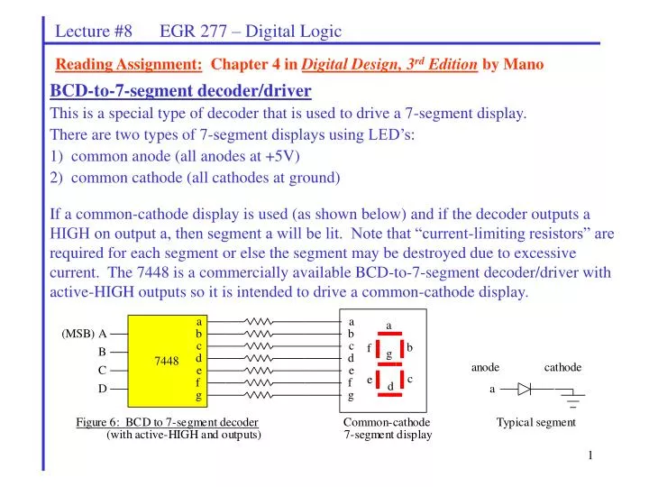
Lecture #8 EGR 277 – Digital Logic Reading Assignment: Chapter 4 in Digital Design, 3rd Edition by Mano BCD-to-7-segment decoder/driver This is a special type of decoder that is used to drive a 7-segment display. There are two types of 7-segment displays using LED’s: 1) common anode (all anodes at +5V) 2) common cathode (all cathodes at ground) If a common-cathode display is used (as shown below) and if the decoder outputs a HIGH on output a, then segment a will be lit. Note that “current-limiting resistors” are required for each segment or else the segment may be destroyed due to excessive current. The 7448 is a commercially available BCD-to-7-segment decoder/driver with active-HIGH outputs so it is intended to drive a common-cathode display.
Lecture #8 EGR 277 – Digital Logic Similarly, a common-anode display requires a driver with active-LOW outputs, such as the 7447. Develop a truth table for designing a BCD-to-7-segment decoder driver.
Lecture #8 EGR 277 – Digital Logic • PSPICE Analysis of Digital Circuits • In EGR 271-272 PSPICE was used to analyze various types of circuits. Several methods of analysis were used, including: • Bias Point Analysis • DC Sweep • AC Sweep • Transient • Parametric • Analysis of logic circuits will only involve transient analysis - in order to generate timing diagrams to show outputs for various combinations of inputs. • Full version of PSPICE: One of the strengths of the full version of PSPICE is that it includes libraries for tens of thousands of components. • Evaluation version of PSPICE: The evaluation version contains a few hundred devices, most of which are 7400 series TTL devices. This is very useful for this course and allows students to analyze circuits using devices that are pin-for-pin compatible with those covered in the text and in lab.
Lecture #8 EGR 277 – Digital Logic 7400 Series parts found in the evaluation library (eval.slb): 7400 Quadruple 2-input Positive-Nand Gates 7401 Quadruple 2-input Positive-Nand Gates with Open-Collector Outputs 7402 Quadruple 2-input Positive-Nor Gates 7403 Quadruple 2-input Positive-Nand Gates with Open-Collector Outputs 7404 Hex Inverters 7405 Hex Inverters with Open-Collector Outputs 7406 Hex Inverter Buffers/Drivers with Open-Collector High-Voltage Outputs 7407 Hex Buffers/Drivers with Open-Collector High-Voltage Outputs 7408 Quadruple 2-input Positive-And Gates 7409 Quadruple 2-input Positive-And Gates with Open-Collector Outputs 7410 Triple 3-input Positive-Nand Gates 7411 Triple 3-input Positive-And Gates 7412 Triple 3-input Positive-Nand Gates with Open-Collector Outputs 7413 Dual 4-input Positive-Nand Schmitt Triggers 7414 Hex Schmitt-Trigger Inverters 7416 Hex Inverter Buffers/Drivers with Open-Collector High-Voltage Outputs 7417 Hex Buffers/Drivers with Open-Collector High-Voltage Outputs 7420 Dual 4-input Positive-Nand Gates 7422 Dual 4-input Positive-Nand Gates with Open-Collector Outputs
Lecture #8 EGR 277 – Digital Logic 7400 Series parts found in the evaluation library (eval.slb): 7423 Dual 4-input Nor Gates with Strobe 7425 Dual 4-input Nor Gates with Strobe 7426 High-Voltage Interface Positive-Nand Gates 7427 Triple 3-input Positive-Nor Gates 7428 Quadruple 2-input Positive-Nor Buffers 7430 8-input Positive-Nand Gates 7432 Quadruple 2-input Positive-Or Gates 7433 Quadruple 2-input Positive-Nor Buffers w/ Open-Collector Outputs 7437 Quadruple 2-input Positive-Nand Buffers 7438 Quadruple 2-input Positive-Nand Buffers w/ Open-Collector Outputs 7439 Quadruple 2-input Positive Nand Buffers with Open-Collector Outputs 7440 Dual 4-input Positive-Nand Buffers 7442A DECODER BCD-DECIMAL 4-10 LINE 7443A DECODER EXCESS-3-DECIMAL 4-10 LINE 7444A DECODER GRAY-DECIMAL 4-10 LINE 7445 DECODER/DRIVER BCD-DECIMAL WITH OPEN COLLECTOR OUTPUTS 7446A DECODER/DRIVER BCD-7 SEGMENT WITH OPEN-COLLECTOR OUTPUTS 7447A DECODER/DRIVER BCD-7 SEGMENT WITH OPEN COLLECTOR OUTPUTS
Lecture #8 EGR 277 – Digital Logic 7400 Series parts found in the evaluation library (eval.slb): 7448 DECODER/DRIVER BCD-7 SEGMENT WITH INTERNAL PULLUPS 7449 DECODER/DRIVER BCD-7 SEGMENT WITH OPEN-COLLECTOR OUTPUTS 7450 Dual 2-wide 2-input And-Or-Invert Gates 7451 And-Or-Invert Gates 7453 Expandable 4-wide And-Or-Invert Gates 7454 4-wide And-Or-Invert Gates 7460 Dual 4-input Expanders 7470 And-Gated J-K Positive-Edge-Triggered Flip-Flops with Preset & Clear 7472 And Gated J-K Master-Slave Flip-Flops with Preset and Clear 7473 Dual J-K Flip-Flops with Clear 7474 Dual D-Type Positive-Edge-Triggered Flip-Flops with Preset and Clear 7475 4-bit bistable latches (dual 2-bit common clock4-bit bistable latches ) 7476 Dual J-K Flip-Flops with Preset and Clear 7477 4-bit bistable latches 7482 2-BIT BINARY FULL ADDERS 7483A 4-BIT BINARY FULL ADDERS WITH FAST CARRY 7485 4-BIT MAGNITUDE COMPARATOR 7486 Quadruple 2-input Exclusive-Or Gates
Lecture #8 EGR 277 – Digital Logic 7400 Series parts found in the evaluation library (eval.slb): 7490A COUNTER DECADE 4-BIT, ASYNCHRONOUS 7491A 8-BIT SHIFT REGISTERS 7492A COUNTER DIVIDE-BY-12 4-BIT, ASYNCHRONOUS 7493A COUNTER BINARY 4-BIT, ASYNCHRONOUS 7494 4-BIT SHIFT REGISTERS 7495A 4-BIT PARALLEL SHIFT REGISTERS 7496 8-BIT PARALLEL-OUT SERIAL SHIFT REGISTERS 74100 8-Bit Bistable Latches 74107 Dual J-K Flip-Flops with Clear 74109 Dual J-KBar Positive-Edge-Triggered Flip-Flops w/ Preset & Clear 74110 And-Gated J-K Master-Slave Flip-Flops with Data Lockout 74111 Dual J-K Master-Slave Flip-Flops with Data Lockout 74121 Non-retriggerable Monostable Multivibrator w/Schmitt-Trigger Inputs 74122 Retriggerable Monostable Multivibrator 74123 Retriggerable Monostable Multivibrator 74125 Quadruple Bus Buffer with 3-state Outputs 74126 Quadruple Bus Buffer with 3-state Outputs 74128 Line Drivers 74132 Quadruple 2-input Positive-Nand Schmitt Triggers
Lecture #8 EGR 277 – Digital Logic 7400 Series parts found in the evaluation library (eval.slb): 74136 Quadruple 2-input Exclusive-Or Gates with Open-Collector Outputs 74145 DECODER/DRIVER BCD-DECIMAL WITH OPEN COLLECTOR OUTPUTS 74147 PRIORITY ENCODER 10-4 LINE 74148 PRIORITY ENCODER 8-3 LINE 74151A MULTIPLEXER/DATA SELECTOR 8-1 LINE 74151A MULTIPLEXER/DATA SELECTOR 8-1 LINE 74154 DECODER/DEMULTIPLEXER 4-16 LINE 74155 DECODER/DEMULTIPLEXER 2-4 LINE 74156 DECODER/DEMULTIPLEXER 2-4 LINE WITH OPEN COLLECTOR OUTPUTS 74157 QUADRUPLE 2-LINE TO 1-LINE DATA SELECTORS/MULTIPLEXERS 74159 DECODER/DEMULTIPLEXER 4-16 LINE WITH OPEN COLLECTOR OUTPUTS 74160 Synchronous 4-bit Decade Counters with asynchronous clear 74161 Synchronous 4-bit Binary Counter with Direct Clear 74162 Synchronous 4-bit Decade Counters with synchronous clear 74163 Synchronous 4-bit Binary Counter 74164 8-BIT PARALLEL-OUT SERIAL SHIFT REGISTERS 74173 REGISTERS D-TYPE 4-BIT WITH 3-STATE OUTPUTS 74174 HEX D-TYPE FLIP-FLOPS WITH CLEAR 74175 QUADRUPLE D-TYPE FLIP-FLOPS WITH CLEAR etc.
T = 2ms A T = 8ms B T = 4ms C T = 2ms Count (ABC): 0 1 2 3 4 5 6 7 0 Lecture #8 EGR 277 – Digital Logic New Parts: The following parts will be introduced: 1) DIGITAL CLOCK – located in the library named SOURCE.OLB Note that the OFFTIME and the ONTIME can be set to produce a waveform with the desired period. For example, the Digital Clock below has a period of 2ms. Similarly, three Digital Clocks could be used to generate waveforms A, B, and C representing the 8 possible input combinations. Since the period of the MSB is 8ms, a transient analysis of 8ms could be used to test circuit outputs for all 8 input combinations.
Lecture #8 EGR 277 – Digital Logic 2) HI and LO inputs – located in the library named SOURCE.OLB Note that a ground is not used in digital circuits and HI and LOW inputs must be produced using these inputs (5V and GROUND will not work). 3) 7400 Series TTL devices – located in the library named EVAL.OLB The EVAL library contains a wide assortment of 7400 series devices. In general, they are pin-for-pin compatible with commercially available devices. For simple logic gates, such as the 7400 NAND, 7402 NOR, 7404 NOT, etc., single gates are inserted rather than an entire IC (a 7400 NAND contains 4 2-input NAND’s). More complex devices match the IC’s exactly. Some examples are shown below.
Lecture #8 EGR 277 – Digital Logic Demonstration: Use ORCAD to demonstrate how to implement a Boolean expression: 1) in SOP form using AND, OR, and NOT gates 2) using a 3x8 decoder