Download
1 / 16
160 likes | 340 Views
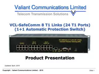
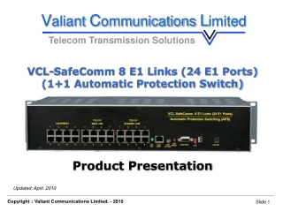
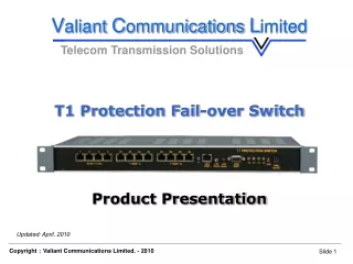
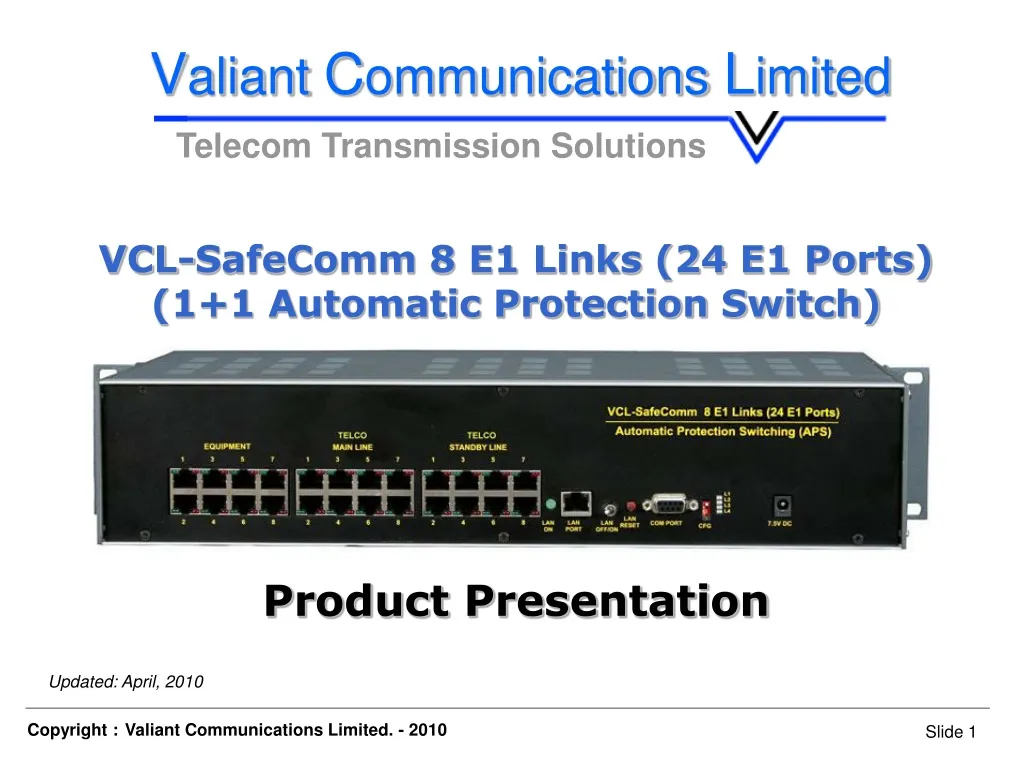
V aliant C ommunications L imited. Telecom Transmission Solutions. VCL-SafeComm 8 E1 Links (24 E1 Ports) (1+1 Automatic Protection Switch) Product Presentation. Updated: April, 2010. Orion Telecom Networks Inc. - 2010. Product Overview.

E N D
Valiant Communications Limited Telecom Transmission Solutions VCL-SafeComm 8 E1 Links (24 E1 Ports) (1+1 Automatic Protection Switch) Product Presentation Updated: April, 2010 Orion Telecom Networks Inc. - 2010
Product Overview • Used to protect upto 8 point-to-point E1 links and to provide an alternate communication route for each E1 Link between any two points in a network • In the event of the failure of the primary (main) E1communication route, the VCL-SafeComm, 8 E1 Links 1+1 APS equipment, automatically switches the E1 traffic to a secondary (standby) E1 route • May also be used in point-to-multi-point applications to provide 1+1 Protected / Alternate Routing Path between multiple locations. • Data transported on the E1 Links is transparent and protocol independent • SNMP V2 Traps for alarm reporting. • Available in a 2U high, 19-Inch rack mount chassis.
Applications: • Allows the user to design 1+1 (protected) redundant E1 routes on similar (fiber-fiber), or complementing (fiber-radio) transmission mediums • Transport A-bis Interface on redundant E1 links • Provide 1+1 Protection / Alternate Routing Path between BSC and BTS • Used to design 1+1 redundant (protected) E1 rings on PDH networks, which otherwise would not be possible with PDH technology • The criterion for switching between the primary (main) and the secondary (protected/standby) routes is user programmable is Loss-Of- Signal on E1 links, or AIS (All-Ones AIS alarm) condition • May be used in a point-to-multipoint configuration to provide 1+1 Protected / Alternate Routing Path between one location and multiple locations (as shown in application diagram).
Features and Highlights: • High density protection switching equipment (upto 8 E1 Links i.e. 24 E1 Ports) • Ensures that mission critical voice, data, control and management traffic links are maintained even if either the primary or the secondary E1 backhaul transmission links fail • When the primary (working) link fails, the E1 traffic is automatically switched to the standby (secondary) link to ensure maximum link uptime • Offers comprehensive remote configuration and alarm management capabilities of the VCL-SafeComm, 8 E1, 1+1 Automatic Protection Switching • Equipment the product may be used to improve network reliability and control • Increased network reliability through link resilience.
Features and Highlights: • Media and Path Diversity • Remote Management • Alarm logging and monitoring • Dual -48V DC Power Inputs. User Programmable 1+1 Protection Switching Parameters: • Loss of Signal • AIS (All Ones Alarm).
Salient Features: • VCL-SafeComm 1+1 Protection Switch does not "add" a point-of-failure to the E1 network. • Even in the event that the power to the VCL-SafeComm 1+1 Protection Switch (or the equipment itself) fails, the E1 link connectivity shall be "always" maintained." The E1 link integrity is ALWAYS maintained (the switch reverts the connection to the primary E1 link), even if the power to the equipment is disconnected and removed. This ensures that the E1 link connectivity is never lost. • VCL-SafeComm 1+1 Protection Switch provides two power inputs and this allows the user to connect the switch to two separate independent -48V DC power sources to minimize the chances of any power failure occurring due to power outage.
Modes of Operation: • There are three modes in which the VCL-SafeComm E1, 1+1 Automatic Protection Switch can be configured to operate in: • AUTOMATIC SWITCHING MODE • EXTERNAL TRIGGER SWITCHING MODE • MANUAL SWITCHING MODE
AUTOMATIC SWITCHING MODE • The VCL-SafeComm can be configured to operate in an AUTOMATIC SWITCHING MODE. In the automatic mode, the switch shall automatically switch and re-route the E1 circuits from the MAIN route to the STANDBY route if there is an AIS or a LOS (LOSS OF SIGNAL) alarm, on the MAIN E1 link route. • Similarly, in the automatic mode the switch shall automatically switch back and re-route the E1 circuits from the STANDBY route to the MAIN route, upon the restoration of the service on the MAIN E1 link route. • All switching parameters and link restoration parameters are user programmable.
EXTERNAL TRIGGER SWITCHING MODE • Sometimes the user wants to switch the E1 circuits between the MAIN route and the STANDBY route when some external event occurs. • In the EXTERNAL TRIGGER MODE, the user can switch between the MAIN E1 route and the STANDBY E1 route when an external trigger (such as an closed/opened physical contact) is applied to the switch. • This unique feature is used by certain radios equipment suppliers, where they apply an external trigger to switch and re-route the E1 circuits between their main E1 radios and standby E1 radios.
MANUAL SWITCHING MODE • In Manual Switching Mode, the user shall use manual Telnet commands to switch the E1 circuits between the MAIN route and the STANDBY route, manually, using Telnet commands. • In this mode the AUTOMATIC MODE and the EXTERNAL TRIGGER MODE are both disabled and the manual commands over ride all other modes.
Switching Criterion and Time E1 Switching Criterion User Programmable 1+1 Protection Criterion a) Loss of Signal b) AIS (All Ones Alarm) Minimum E1 Switching Time from 10 ms. to 3000 ms. (User Programmable) Main Link To Standby Link Minimum E1 (Recovery) Switching 10 ms. to 9999 ms. (User Programmable) Time From Standby Link to Main Link Switching Mode User can program the APS to stay on Standby Port a) Auto when the Main link is restored. b) Force ON Main c) Force ON Standby
Application Diagram - To provide redundant routes over diverse media: SafeComm 8 E1 Links (24 E1 Ports)
Thank you for your attention For more details visit us at our Website at http://www.valiantcom.com INDIA Valiant Communications Limited71/1, Shivaji Marg, New Delhi - 110015, India Phone: +91-11 4105 5601, 91-11 4105 5602 Fax: +91-11 4105 5604, 91-11 2543 4300 E-mail: getinfo@valiantcom.com Website: http://www.valiantcom.com U.K. Valiant Communications (UK) Ltd 1, Acton Hill Mews, 310-328 Uxbridge Road, London W3 9QN, United Kingdom E-mail: gb@valiantcom.com Website: http://www.valiantcom.com U.S.A. Valcomm Technologies Inc. 4000 Ponce de Leon, Suite 470Coral Gables, FL 33146United States of America E-mail: us@valiantcom.com Website: http://www.valiantcom.com