Download
1 / 42
420 likes | 509 Views
TNN CAR CD PLAYER SOLUTION CD-ESP MODEL. 2004.02. TEL : (8231)715-4611 FAX : (8231)715-4612. 1. FEATURES 2. BLOOK DIAGRAM 3. PIN DIAGRAM 4. PIN DESCRIPTIONS 5. OPTION DIODE AND KEY MATRIX 6. RADIO MODE 7. CDP MODE

E N D
TNN CAR CD PLAYER SOLUTION CD-ESP MODEL 2004.02 TEL : (8231)715-4611 FAX : (8231)715-4612
1. FEATURES 2. BLOOK DIAGRAM 3. PIN DIAGRAM 4. PIN DESCRIPTIONS 5. OPTION DIODE AND KEY MATRIX 6. RADIO MODE 7. CDP MODE 12. VOLUME MODE 13. POWER OFF / DOWN MODE CONTENTS TNN SOLUTION CO., LTD.
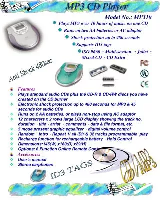
1. FEATURES MAIN FEATURES [ Main features and characteristics ] - CDRW, CD-R, CD Disc playback - Shock proof function (ESP) ▶ 45sec(16M) - MK(Manufacturing Kit) board level - Provide high flexiblity ▶ Compatible with various CD CAR CD DECK - Compact Design ▶ Small size LSI package Reduced # of external components such as capacitor, resistor etc TNN SOLUTION CO., LTD.
RADIO FUNCTIONS (1) RECEIVING FREQUENCY, CHANNEL SPEACE (2) TUNER UP / DOWN FUNCTIONS • Key less than 2sec - SEEK UP/DOWN • Key more than 2sec - 1STEP UP/DOWN TNN SOLUTION CO., LTD.
(3) SEEK FUNCTIONS Used to search a broadcasting station automatically and hold a receiving frequency when the broadcasting station is reached. (4) PRESET · MEMORY · SCAN Preset memory 5 sec receiving. (5) PRESET MEMORY When the LW band is used, MW2 cannot be used (6) STORE · CHANNEL · MEMORY FM1, FM2, FM3,OIRT,MW1,MW2,LW (7) LOC (Local) control output and display. (8) Auto Store Memory (ASM) (9) “ • FM band - FM1 : 6 stations, FM2 : 6 stations, FM3 : 6 stations • OIRT band - FM : 6 stations • MW band - MW1 : 6 stations, MW2 : 6 stations • LW band - LW : 6 stations ” / “ST”display at FM band. TNN SOLUTION CO., LTD.
CDP FUNCTIONS • “ CD ” display • CD-R/RW, Play is possible • ELECTRIC VOLUME CONTROL FUNCTIONS • (1) VOLUME / BASS / TREBLE / BALANCE / FADER selectable • (2) Full function display on LCD panel. • (3) MUTE function. • (4) LOUDNESS control and display. • (5) Initial volume adjustment function. • (6) Each function can maintain its own volume level • AUX FUNCTION • “AUX” display. • OPTION DIODE • (1) AREA1,2,3 : Reception area setting switch. • (2) ENOIRT / ENLW : Receiving radio band setting switch. • (3) AUX ON/OFF : FUNCTION selection switch. • (4) FMIF-SD / AMIF-SD : SD detect and SD+IF detect method are decided • (5) MWIF 1071 : MW IF 10.71MHz TNN SOLUTION CO., LTD.
CAR CD-MP3 BLOCK DIAGRAM PICKUP MECHA SHINHEUNG 4CH DRIVER (9259) RF-AMP+SSP (S1L9226) CD-R, CD-RW DSP+DAC (S5L9291) 1BIT DAC DRAM 16MDRAM LINE OUT MICOM (S3C8325-XX) PT2313 ◎L ◎R TEXT-LCD (12*2+ICONS) KEY (PANEL &REMOCON)
3. PIN DIAGRAM POWER/P1.3 P1.2 REMO/P1.0 STIN/P0.7 ACCIN/P0.5 MCLK/P0.2 VDDPLL SQCK/P1.4 CDPON/P0.6 DSENS/P0.4 SSENS/P0.3 MXLT/P0.0 CE EO SCOR/P1.1 MDAT/P0.1 81 82 83 84 85 86 87 88 89 90 91 92 93 94 95 96 97 98 99 100 80 79 78 77 76 75 74 73 72 71 70 69 69 68 67 66 65 1 FMIF LIMIT SW/P1.5 64 SUBQ/P1.6 2 AMIF 63 DET SW/P1.7 62 VSSPLL 3 1 VCOAM 61 EJ SW/P2.0 4 2 80 79 78 77 76 75 74 73 72 71 70 69 68 67 66 65 64 63 62 61 60 59 58 57 56 55 54 53 52 51 60 VCOFM LD SW/P2.1 5 3 59 P3.3/RADIO ON OP SW/P2.2 6 4 58 P3.2/AGC CL SW/P2.3 7 5 57 P3.1/BAND1 EQ 1/P2.4 8 6 56 EQ 2/P2.5 P3.0/BAND2 9 7 P4.7/OPMTR EQ 3/P2.6 10 55 8 S3C8325 80-QFP-1420 54 P4.6/CLMTR SD IN/P2.7 11 9 53 P4.5/ENCODER DN VDD 1 12 10 P4.4/ENCODER UP VSS 1 13 52 S3C8325 80-QFP-1420 11 51 P4.3 XOUT 14 12 50 XIN P4.2 15 13 49 TEST0 P4.1/SCLK (LCD) 16 14 P4.0/CE (LCD) 48 XT IN 17 15 47 XT OUT P5.7/EJECT 18 16 RESET 46 P5.6/SO(LCD) 19 17 P5.5/SI(LCD) LPF 45 20 18 44 P5.4 TEST1 21 19 VDD2 22 43 P5.3 20 VSS2 42 P5.2 23 21 LOC/P8.0 24 P5.1 41 22 23 25 26 27 28 29 30 31 32 33 34 35 36 37 38 39 40 P6.6/OPT6 P6.7/OPT7 P5.0/XRST P8.1/MUTE P8.2/EVOL_CLK P8.3/EVOL_DAT P7.0/KIN0 P7.1/KIN1 P7.2/KIN2 P7.3/LKFS P6.0/OPT0 P6.1/OPT1 P6.2/OPT2 P6.3/OPT3 P6.4/OPT4 P6.5/OPT5 TNN SOLUTION CO., LTD.
4. PIN DESCRIPTIONS TNN SOLUTION CO., LTD.
● ▲ Diode matrix Momentary switch 5. OPTION DIODE AND KEY MATRIX 5.1 TABLE CONFIGURATIONS TNN SOLUTION CO., LTD.
5.2 OPTION DIODE DESCRIPTIONS TNN SOLUTION CO., LTD.
6. KEY FUNCTION TNN SOLUTION CO., LTD.
Mute 300ms M3 on M3 off 2sec M1 89.1 89.1 6. RADIO MODE 6.1 RADIO KEY DESCRIPTIONS (1) M1, M2, M3, M4, M5, M6 It performs preset memory read / write function. WRITE operation. One of the M1 ~ M6 key is pressed for more than 2 seconds, current frequency is stored to corresponding memory area. -When write operation, It performs 0.3 sec mute operation. These keys are invalid when AUTO MEMORY operation. ■ READ operation One of the M1~M6 key is pressed for less than 2 seconds, read the corresponding preset memory. Mute 300ms M3 off M3 on M1 89.1 91.9 - These keys are invalid when AUTO MEMORY operation TNN SOLUTION CO., LTD.
Initial frequency to the preset memory. Other bands : Minimum frequency of each area is memorized. (2) AME / PSCAN Preset memory scan / Auto store memory key. When AME / PSCAN key is pressed for less than 1 sec, it performs preset memory scan function. When AME / PSCAN key is pressed for more than 1sec, it performs auto store memory function. 1) preset memory scan function descriptions Reading preset memory in regular frequency for 5 seconds each. Ex1) Current receiving frequency : FM1, CH3 Key on M3 M4 M6 M5 FM1 FM1 M1 M2 PSCAN operation stop • If AME / PSCAN key is pressed again during preset memory scan operation, it stop • preset memory scan operation and maintain the current frequency • - When reading preset memory, mute is active for 300msec TNN SOLUTION CO., LTD.
Ex 2) FM1 90.1MHz ( M1 : 89.1, FM2 : 91.9 …....… . ) Mute 5SEC AME PSCAN AME PSCAN Key 90.1 89.1 91.9 93.1 Display 22) Auto store memory function descriptions. - During SEEK UP operation with station detection, if any station is detected, then this detected station is automatically stored to the corresponding preset memory area in regular frequency. - Current receiving frequency is preset memory : From current channel to M6 - Current receiving frequency is not preset memory : Form M1 to M6 - During Auto store memory, mute pin has low level. - When this operation is finished, it performs preset memory scan operation for one time. TNN SOLUTION CO., LTD.
- Station search is executed two times (LOC : 1 time, DX : 1 time) - During this operation, if preset memory is fully stored from M1 to M6 then stop this operation and performs preset memory scan one time (Even though three times station search is not completed) Ex 1) FM1 88.0 MHz ( M1 : 89.1, FM2 : 91.9 …....… . ) TNN SOLUTION CO., LTD.
(3) SEEKUP ■ SEEKUP function When any of SEEK UP key is pressed, the frequency moves up by one channel step with station detection. As this time, if a valid signal has detected, maintain the current frequency. If not, performs seek operation continuously. “ LOC ” display on LOCAL mode LOCAL mode ∫ station detection LOCAL mode “ LOC ” display off DX mode DX mode ∫ station detection DX mode TNN SOLUTION CO., LTD.
Mute Display 89.1 89.2 90.1 90.2 200m …… 100m 300m Time 2sec Key TUNUP Key off (4) TUNUP / TUNDN TUNER TUNING. If TUNUP / TUNDN key is pressed for more than 1 second, enter the “MANUAL” mode. Whenever one of TUNUP / TUNDN key is pressed, the frequency moves up / down by one channel step. If there is no key input during 5sec, it cancels “MANUAL” mode. Mute Display 89.1 89.2 Time Key TUN UP Key off 2sec TNN SOLUTION CO., LTD.
(5) SCAN UP LOCAL mode SCAN UP functions. DX mode ① When SCAN UP key is pressed, the frequency is scan up by one channel step with station detection. ② If a valid signal has detected, the current frequency is blinked each 500mesc with in 5 seconds. If this case, SCAN UP key is pressed, SCAN function is released and the current frequency is maintained. ③ When SCAN UP key is not pressed with in blinking, the frequency moves up by one channel step with station detection. (6) BAND Band changes key. Band change over is performed through the cyclic method with the Band key. (7) LOC LOC (Local) function control key. This key is valid only in RADIO mode The “ LOC ” is toggled on LCD panel at every key input TNN SOLUTION CO., LTD.
6.2 RADIO DISPLAY (1)FM BAND Local indicator Stereo signal indicator BAND Display Frequency display (2)AM BAND (3)CHANNEL TNN SOLUTION CO., LTD.
(4) MANUAL MODE (5) AUTO MODE
7. CDP MODE 7.1 CDP KEY DESCRIPTIONS (1) M1/PLAY / PAUSE CDP Play / Pause key (2) M2 / SCN Intro scan on / off key It play individually time for 10 seconds. it display “ S-SCN ”. (3) M3 / RPT Repeat play on / off key it display “ S-RPT ” (4) M4 / SHF SHUFFLE play on / off key If this key is pressed, SHUFLE function performs. it display “ S-SHF ” (5) CDP EJT CDP Eject key. TNN SOLUTION CO., LTD.
(7) T-UP Track forward key It moves to next tune and if it meet to last tune then it goes to first tune. If this key is pressed in shuffle play mode, it performs shuffle select function. If this key is pressed for more than 0.8 sec, it changes to search FF mode. (8) T-DN Track downward key The running time of current playing tune is less than 1 seconds, it moves to last tune. The running time of current playing tune is more than 1 seconds, it moves to first of current tune. If this key is pressed in shuffle play mode, it performs shuffle select function. If this key is pressed for more than 0.8 sec, then it changes to search FR mode. TNN SOLUTION CO., LTD.
7.2 CDP DISPLAY (1)CDP Initial mode (2)During CDP mode (3)During Intro mode TNN SOLUTION CO., LTD.
(4)During Repeat mode (5)During Shuffle mode (6)During Pause mode
(6) When mecha error (7) When Servo error
9. VOLUME MODE 12.1 VOLUME KEY DESCRIPTIONS (1) VOLSEL VOLUME mode control key (2) VOLUP, VOLDN Volume level up / down key (3) LOUD Loudness on / off control key (4) MUTE Mute on / off control key When “ MUTE ” is displayed, mute port output low level. (5) DSP SURROUND mode change key. This key is available with TDA7313 Initial state is SURROUND OFF mode. 12.2 VOLUME MODE ON/OFF It is automatically released after 5 seconds from volume control 12.3 VOLUME LEVEL INITIAL VALUE • TDA7313 • Volume - Level = dB step • Bass - Level = 0, dB step = 0 • Balance - Level = 0, dB step = 0 • Fader - Level = 0, dB step = 0 TNN SOLUTION CO., LTD.
12.4 TDA7313/KB22501 LEVEL TABLE (1) VOLUME ( TDA7313 ) TNN SOLUTION CO., LTD.
-7 -6 -5 -4 -3 -2 -1 0 1 2 3 4 5 6 7 -14 -12 -10 -8 -6 -4 -2 0 2 4 6 8 10 12 14 DISPLAY STEP (Db) (2) BASS / TREBLE (TDA7313) ■ TDA7313 (3) BALANCE / FADER (TDA7313 ) ■ TDA7313 0 1 2 3 4 5 6 7 8 9 10 0 -1.25 -2.5 -5 -7.5 -11.25 -15 -20 -25 -31.25 ∞ DISPLAY STEP (Db) TNN SOLUTION CO., LTD.
12.5 VOLUME DISPLAY (1)Volume (2)Bass (3)Treble TNN SOLUTION CO., LTD.
(4)Balance (5)Fader (6)LOUD TNN SOLUTION CO., LTD.
(7)CLASSIC (8)ROCK (9)POP
RADIO mode POWER key push MAX 0.3sec wait POWER OFF mode POWER key push MAX 0.3sec wait RADIO mode 13. POWER OFF/DOWN MODE 13.1 POWER OFF MODE If POWER key is pressed in RADIO / CDP mode, it goes to POWER OFF mode. Low level output to power pin and LCD off Detachable type : front panel removed from main system it goes to POWER OFF mode also. If POWER key is pressed again or front panel is attached to main system in POWER mode, it recovers to same mode as before. Ex1) POWER key is pressed in RADIO mode. TNN SOLUTION CO., LTD.
RADIO mode ACC IN = High Low MAX 0.3sec wait POWER DN mode ACC IN = Low High MAX 0.3sec wait RADIO mode 13.2 POWER DOWN MODE • The ACC IN pin goes to low cause by ACC off, it goes to POWER DOWN mode. • If ACC IN pin goes to high level at POWER DOWN mode caused by ACC on, it recovers to same mode as before. • Ex2) power down in RADIO mode. TNN SOLUTION CO., LTD.