Download
1 / 67
700 likes | 930 Views
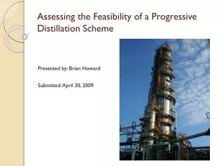
EVALUATION OF PROGRESSIVE DISTILLATION. Dan Dobesh – Jesse Sandlin Dr. Miguel Bagajewicz 04.29.2008. This presentation is not about this Insurance Company. Not about this one either…. Our Mission.

E N D
EVALUATION OF PROGRESSIVE DISTILLATION Dan Dobesh – Jesse Sandlin Dr. Miguel Bagajewicz 04.29.2008
Our Mission “Analyze progressive crude fractionation, a technology patented in 1987 that claims to be more energy efficient than conventional fractionaltion.”
Punchline “Progressive Distillation can reduce the heat duty requirement of the distillation process by 17% for a heavy crude, and use 16% less furnace heat utility while producing more valuable products for a light crude.”
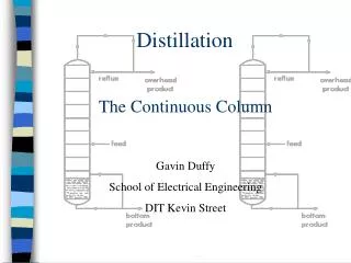
Overview • Background: • Distillation Specifications • Conventional Crude Distillation • Progressive Crude Distillation • Methodology • Results • Accuracy & Limitations
Petroleum Value Chain Petroleum Refining Petroleum Products Petroleum Production http://en.wikipedia.org/wiki/Oil_refinery www.freddiesasphaltoval.com/ Fuels Solvents Lubricants Plastics Detergents Nylon Polyesters http://www.lakewoodconferences.com/direct/dbimage/50241031/Plastic_Toy.jpg http://en.wikipedia.org/wiki/Image:Oil_well.jpg www.ehow.com/how_2041839_siphon-gas-car.html
Oil Refinery Schematic Over 2% of the energy content in a crude stream is used in distillation.* Distillation accounts for about 40% of energy use in a refinery.** Diagram Source: http://en.wikipedia.org/wiki/Oil_refinery * Bagajewicz, Miguel and Ji, Shuncheng. “Rigorous Procedure for the Design of Conventional Atmospheric Crude Fractionation Units. Part I: Targeting.” Ind. Eng. Chem. Res. 2001, 40, 617-626 **Haynes, V.O. “Energy Use in Petroleum Refineries.” ORNL/TM-5433, Oak Ridge NationalLaboratory, Tennessee, September (1976).
Overview • Background: • Distillation Specifications • Conventional Crude Distillation • Progressive Crude Distillation • Methodology • Results • Accuracy & Limitations
Light Crude Feed • Petroleum crude component boiling points range from -161 C (CH3) to over 827 C (C40H82+)
Heavy Crude Feed • Petroleum crude component boiling points range from -161 C (CH3) to over 827 C (C40H82+)
ASTM D86-07b, “D86 Point” • American Society for Testing and Materials (ASTM): international organization that is a source for technical standards • Rigorously developed method for quantitatively testing the boiling range of a petroleum product (1) Oil sample heated in glass flask using electric heater (2) Vapor is condensed and collected (3) Temperature versus amount collected is recorded • Not applicable to products containing large amounts of residual
ProductSpecifications Generated from Pro/II Computer Model This graph compares the boiling point range of the five products
Product Gaps Explanation D86 5% point heavy component - D86 95% point light component 390⁰ C - 360⁰ C = 30⁰ C D86 95% point light component D86 5% point heavy component Positive gaps indicate more distinct separation.
Overview • Background: • Distillation Specifications • Conventional Crude Distillation • Progressive Crude Distillation • Methodology • Results • Accuracy & Limitations
Gaps – Conventional Distillation D86 95% point anchors products on the right side, gaps change the left side
Conventional = Indirect Takes the heaviest component as the bottom product in each column. Lighter components are sent to the next column. Source: Smith, Robin, Chemical Process Design
Conventional = Indirect Stacking these columns on top of each other is essentially conventional distillation. Bagajewicz, Miguel and Ji, Shuncheng. “Rigorous Procedure for the Design of Conventional Atmospheric Crude Fractionation Units. Part I: Targeting.” Ind. Eng. Chem. Res. 2001, 40, 617-626
Conventional = Indirect Stacking these columns on top of each other is essentially conventional distillation. Stacked columns from the indirect sequence. Bagajewicz, Miguel and Ji, Shuncheng. “Rigorous Procedure for the Design of Conventional Atmospheric Crude Fractionation Units. Part I: Targeting.” Ind. Eng. Chem. Res. 2001, 40, 617-626
Overview • Background: • Distillation Specifications • Conventional Crude Distillation • Progressive Crude Distillation • Methodology • Results • Accuracy & Limitations
Patent: Process for Distillation of Petroleum by Progressive Separations • This is an expired patent for crude fractionation that is now being commercialized by Technip. • Main idea is to heat components only as much as necessary. • Several companies are excited by this concept that promises large energy savings. • A new refinery is being built in central Germany using this concept.
Gaps – Progressive Distillation Light Crude
Progressive = Direct Takes the lightest component as the top product in each column. Heavier components are sent to the next column. Source: Smith, Robin, Chemical Process Design
Conventional vs. Progressive Summary One main column Many columns Direct Indirect Recover heavy components first Recover light components first
Overview • Background: • Distillation Specifications • Conventional Crude Distillation • Progressive Crude Distillation • Methodology • Results • Accuracy & Limitations
Simulation Development Method • Build PRO/II progressive crude simulation • Obtain correct D86 95% points • Synchronize product gaps • Mimimize heat duty • Compare to conventional heat duty • Determine areas for improvement
Simulation Assumptions • SRK is a valid thermodynamic model for hydrocarbon systems • Pseudocomponents represent crude composition • PRO/II provides a close representation of reality
Basis of Comparison PRO/II Conventional Simulation, 260 ⁰C steam
PRO/II Computer Model(s) Progressive Model – 4 column direct Furnace heat duty = 89 MW This is higher than 58.7 MW for conventional distillation Previous work suggested that this setup provided no furnace heat utility benefit over conventional distillation. Our results verify this.
Initial Complex Simulation • Unnecessarily complicated Too many products for conventional comparison
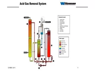
PRO/II Computer Model Patent Vacuum distillation for residual product is not important for comparison
Second Type Simulation • Too much furnace heat utility: 200+ MW Each column has a reboiler
Third Type Simulation • Furnace utility is lower, but steam utility his very high All seven columns have steam input
Heating Supply-Demand F*Cp MW Temperature ⁰C • Demand Curve – dark line showing heat needed by system • Supply boxes – heat utility able to be recovered from system • Heat can be transferred down and left by second law • Heat can only move right across pinch via a pumparound
Final Type Simulation Replaced steam with reboilers in the first series of columns
Heating Supply-Demand F*Cp MW Temperature ⁰C
Controller-Variable Systems • Naphtha-kerosene gap varies with steam flowrate in Column 1 • Kerosene-diesel gap varies with steam flowrate in Column 2 • Diesel-gas oil gap varies withsteamflowrate in Column 3 • D86 95% points are obtained by varying the condenser duty Column 2 Column 1 Column 3
days… MONTHS weeks After hours of red simulations and Red Bulls… After hours of red simulations and Red Bulls… After hours of red simulations and Red Bulls… After hours of red simulations and Red Bulls… Happy hour
Final Simulations • Conventional: four simulations • 260 ⁰C steam, 135 ⁰C steam • Heavy feed, light feed • Progressive: eight simulations • Reboilers, steam • 260 ⁰C steam, 135 ⁰C steam • Heavy feed, light feed • High heat exchanger temperatures, low heat exchanger temperatures
Overview • Background: • Distillation Specifications • Conventional Crude Distillation • Progressive Crude Distillation • Methodology • Results • Accuracy & Limitations