Download
1 / 30
300 likes | 434 Views
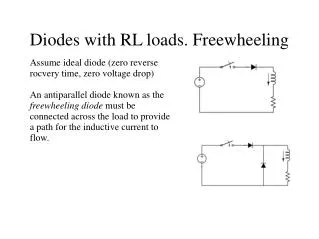
SRF Results and Requirements cavities , coupler, tuner, HOM loads, & SC magnet . MLC Review October 3, 2012. One-Cavity Unit. Beamline HOM absorber. SRF cavity inside LHe tank. RF input coupler. Cavity frequency tuner. SRF Cavity. ERL Main Linac SRF Cavity.

E N D
SRF Results and Requirementscavities, coupler, tuner, HOM loads, & SC magnet MLC Review October 3, 2012 Matthias Liepe
One-Cavity Unit BeamlineHOM absorber SRF cavity inside LHe tank RF input coupler Cavity frequency tuner Matthias Liepe
SRF Cavity Matthias Liepe
ERL Main Linac SRF Cavity Matthias Liepe
Prototype Cavity Fabrication Electron Beam Welding Finished main linac cavity with very tight (±0.25 mm) shape precision important for supporting high currents (avoid risk of trapped HOMs!) Matthias Liepe Quality control: CMM and frequency check
HGRP 80K shield Full System Test of a 1-Cavity Main Linac Unit in a Cryomodule cavity HOM load HOM load Gate valve • First full main linac system test • 1st test: cavity and tuner only (completed) • 2nd test: add high power RF input coupler (under test) • 3rd test: add HOM beamline loads (next year) Test cryomodule installed at Wilson Lab Matthias Liepe
1st Cryomodule Test of ERL Main Linac Cavity (with high Qext input coupler) Cavity surface was prepared for high Q0 while keeping it as simple as possible: bulk BCP, 650C outgassing, final BCP, 120C bake Administrative limit. Cavity can go to higher fields Cavity exceeds ERL gradient and Q0specifications: Q0=4 to 61010 at 1.6K in a cryomodule! Matthias Liepe
2ndCryomodule Test of ERL Main Linac Cavity (with RF input coupler) Quality factor Q0 Q0 ~ 2*1010 at 16 MV/m and 1.8 K Eacc [MV/m] Matthias Liepe
High Q0 Results from Elsewhere 9-cell Cavity test in Horizontal Test Cryostat at HZB Average performance of eight 9-cell cavities in a FLASH cryomoduleat DESY 1.6K 1.8K 2K Q0 ~ 2*1010 at 16 MV/m and 1.8 K Q0 > 2*1010 at 16 MV/m and 1.8 K Matthias Liepe
1.00 0.50 X1 [mm] 0.00 X position [mm] X3 [mm] ERL Injector Cooldown WPM Horizontal X4 [mm] -0.50 X5 [mm] -1.00 4/29/08 0:00 4/30/08 0:00 5/1/08 0:00 5/2/08 0:00 Date-Time Alignment Results from the Injector Cryomodule using fixed Supports • High precision supports on cavities, HOM loads, and HGRP for “self” alignment of beam line • Rigid, stable support • Shift of beamline during cool-down as predicted • Cavity string is aligned to 0.2 mm after cool-down! Matthias Liepe
MLC Requirements: Cavities • RF performance: • 16.2 MV/m (13 MV) average (5GeV from 384 cavities) • 20 MV/m max (16 MeV) for overhead • Q0 = 2*1010 on average at 16.2 MV/m (~11 W per cavity) • Cryosystem should support individual cavities with Q0>5*109 • Cryosystem should support individual cryomodules with Q0,avg= 1*1010 • Magnetic field at cavity location should be < 3 mGfor Rres<1 nOhm • Field stability (assuming non-correlated errors): • Allowable relative amplitude error: (1 sigma) 6*10-3 • Allowable phase error: (1 sigma): 1 deg Matthias Liepe
MLC Requirements: Cavities • Alignment: • Cavities: • Allowable transverse offset (x,y): (1 sigma) 2 mm • Allowable pitch (1 sigma): 1.5 mrad(1.2 mm over length of cavity) • Quadrupole: • Allowable transverse offset (x,y): (1 sigma): 1.6 mm Matthias Liepe
Input Coupler Matthias Liepe
Main Linac RF Input Coupler Design Waveguide Flange Warm Ceramic Window Air Cooling 300K Flange 40K Flange and cooling Bellows Cavity Flange (1.8K) Instrumentation Port Pump Port Antenna 5K Intercept Cold Ceramic Window Matthias Liepe
Beamline: Input Coupler • 2 kW average RF power • 5 kW peak RF power • Fixed coupling • Large transverse flexibility (~1 cm transverse motion during cool down) • 5K and 40 – 80 K intercepts Matthias Liepe
Main Linac RF Input Coupler Prototype and Test • Prototype fabricated and tested successfully • Tested up to full power specification of 5 kW CW Matthias Liepe
MLC Requirements: RF Input Coupler • RF input coupler: • 5kW peak • 2 kW CW average • Fixed coupling with Qext = 6.5*107 • >1 cm transverse flexibility for motion during cool down • Cryoloads per coupler: 0.1W at 1.8K, 1W at 5K, 10W at 40K Matthias Liepe
Frequency Tuner Matthias Liepe
Design of Main Linac Cavity Frequency Tuner • Design optimized for CW cavity operation with very high loaded quality factor • High stiffness • Fast piezo actuators for fast control of cavity frequency Stepper motor for slow control Stresses at 26 kN tuner force Piezoelectric actuators for fast control Matthias Liepe
Frequency Tuner • Prototype tested successfully with prototype main linac cavity in test cryomodule • Excellent stiffness and linearity with very small hysteresis • >400 kHz slow tuning range • 2 kHz fast piezo tuning range Matthias Liepe
HGRP 80K shield Microphonics Results From the HTC and Elsewhere cavity HOM load HOM load Gate valve Sigma = 4.6 Hz Peak = 18 Hz Matthias Liepe
MLC Requirements: Frequency Tuner • Frequency tuner and microphonics: • Slow tuner range: ~500 kHz • Fast tuner range: >1 kHz • Peak microphonics detuning: <20 Hz • Sigma ~ 3.3 to 4 Hz (assuming peak = 5 to 6 sigma) • Peak detuning counts (determines maximum RF power)! • 5 kW sufficient for 16.2 MV/m and 20 Hz detuning Matthias Liepe
HOM Beamline Load Matthias Liepe
HOM Beamline Absorber Flange for disassembly 40 to 80K intercept • Broadband SiC absorber ring • Full-circumference heat sink to allow >500W dissipation @ 40K • Includes bellow sections • Flanges allow easy cleaning • Zero-impedance beamline flanges 5K intercept SiC absorber ring brazed to metal ring Flange to cavity Shielded bellow Matthias Liepe
HOM BeamlineAbsorbers Cavityat 1.8K HOM load at 40 to 80K Cavityat 1.8K 5K intercept 5K intercept 40 to 80K intercept Matthias Liepe
MLC Requirements: HOM Load • Beam and HOM damping: • Maximum beam current: 2 * 100 mA (ERL mode) • Bunch charge: 77 pC • Bunch length: 0.6 mm (2 ps) • Longitudinal loss factor of cavity: 13.1 V/pC • Average HOM power per cavity: 200 W at 40K • Peak HOM power per cavity: >400 W at 40K • Average HOM power per module: ~1.4 kW at 40K Matthias Liepe
SC Magnet Matthias Liepe
Superconducting Magnet • One superconducting quadrupole • X-Y dipoles • Cooled at 1.8 K Matthias Liepe
MLC Requirements: SC Magnet • Superconducting quadrupole • Operating temperature: 1.8 K • Maximum current: 110 A • Maximum gradient: 19.4 T/m Matthias Liepe
The End Matthias Liepe