Download
1 / 1
10 likes | 127 Views
Characterisation and Optimisation of the ALICE Accelerator as an Injector for the EMMA NS-FFAG. THPD030. J.M. Garland* , H.L. Owen, J.W. McKenzie, B.D. Muratori. Abstract. Measurements in the ALICE Injector. GPT Simulations.

E N D
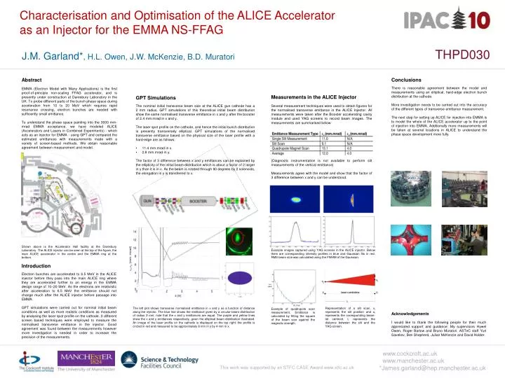
Characterisation and Optimisation of the ALICE Acceleratoras an Injector for the EMMA NS-FFAG THPD030 J.M. Garland*, H.L. Owen, J.W. McKenzie, B.D. Muratori Abstract Measurements in the ALICE Injector GPT Simulations EMMA (Electron Model with Many Applications) is the first proof-of-principle non-scaling FFAG accelerator, and is presently under construction at Daresbury Laboratory in the UK. To probe different parts of the bunch phase space during acceleration from 10 to 20 MeV which requires rapid resonance crossing, electron bunches are needed with sufficiently small emittance. To understand the phase space painting into the 3000 mm-mrad EMMA acceptance, we have modeled ALICE (Accelerators and Lasers in Combined Experiments) - which acts as an injector for EMMA - using GPT and compared the estimated emittances with measurements made with a variety of screen-based methods. We obtain reasonable agreement between measurement and model. • The nominal initial transverse beam size at the ALICE gun cathode has a 2 mm radius. GPT simulations of this theoretical initial beam distribution show the same normalised transverse emittance in x and y after the booster of 2.4 mm.mrad in x and y. • The laser spot profile on the cathode, and hence the initial bunch distribution is presently transversely elliptical. GPT simulations of the normalised transverse emittance based on the physical size of the laser profile with a hard-edge are as follows: • 11.4 mm.mrad in x. • 2.8 mm.mrad in y. • The factor of 3 difference between x and y emittances can be explained by the ellipticity of the initial beam distribution which is about a factor of 2 larger in y than it is in x. As the beam is rotated through 90 degrees by 2 solenoids, the elongation in y is transferred to x. Conclusions There is reasonable agreement between the model and measurements using an elliptical, hard-edge electron bunch distribution at the cathode. More investigation needs to be carried out into the accuracy of the different types of transverse emittance measurement. The next step for setting up ALICE for injection into EMMA is to model the whole of the ALICE accelerator up to the point of injection into EMMA. Additionally more measurements will be taken at several locations in ALICE to understand the phase space developmentmore fully. Example images captured using YAG screens in the ALICE injector. Below them are corresponding intensity profiles in blue and Gaussian fits in red. RMS beam size was calculated using the FWHM of the Gaussian. Representation of a slit scan, xi represents the slit position and ui represents the corresponding beam-let centroid. L represents the distance between the slit and the YAG screen. Example of quadrupole scan measurement. Emittance is calculated by fitting the square of the beam size against the magnetic strength. Shown above is the Accelerator Hall facility at the Daresbury Laboratory. The ALICE injector can be seen at the top of the figure, the main ALICE accelerator in the centre and the EMMA ring at the bottom. Several measurement techniques were used to obtain figures for the normalised transverse emittance in the ALICE Injector. All measurements were taken after the Booster accelerating cavity module and used YAG screens to record beam images. The measurements are summarised below: (Diagnostic instrumentation is not available to perform slit measurements of the vertical emittance) Measurements agree with the model and show that the factor of 3 difference between x and y can be understood. Introduction Electron bunches are accelerated to 6.5 MeV in the ALICE injector before they pass into the main ALICE ring where they are accelerated further to an energy in the EMMA design range of 10–20 MeV. As the electrons are relativistic after acceleration to 6.5 MeV the emittance should not change much after the ALICE injector before passage into EMMA. GPT simulations were carried out for nominal initial beam conditions as well as more realistic conditions as measured by analysing the laser spot profile on the cathode. 3 different screen based techniques were employed to measure the normalised transverse emittance in the injector. Good agreement was found between the measurements however more investigation is needed in order to increase the precision of the measurements. Acknowledgements I would like to thank the following people for their much appreciated support and guidance: My supervisors Hywel Owen, Roger Barlow and Bruno Muratori. ASTeC staff Yuri Saveliev, Ben Shepherd, Julian McKenzie and David Holder. The left plot shows transverse normalised emittance in x and y as a function of distance along the injector. The blue line shows the emittance given by a circular beam distribution of radius 2 mm, note that the x and y emittances are equal. The purple and yellow lines show the x and y emittances respectively, given the elliptical beam distribution illustrated. An image of the laser profile on the cathode is displayed on the top right: the profile is circled in red and measured to be approximately 8 mm in y by 4 mm in x. www.cockcroft.ac.uk www.manchester.ac.uk *James.garland@hep.manchester.ac.uk This work was supported by an STFC CASE Award www.stfc.ac.uk